Measurement Principle:
The LSU-99A Series Gas Vortex Flow Meter operates on the Kármán vortex street principle. It combines the characteristics of both vortex flowmeters and electromagnetic flowmeters, which belong to the category of velocity-type flow measurement instruments.
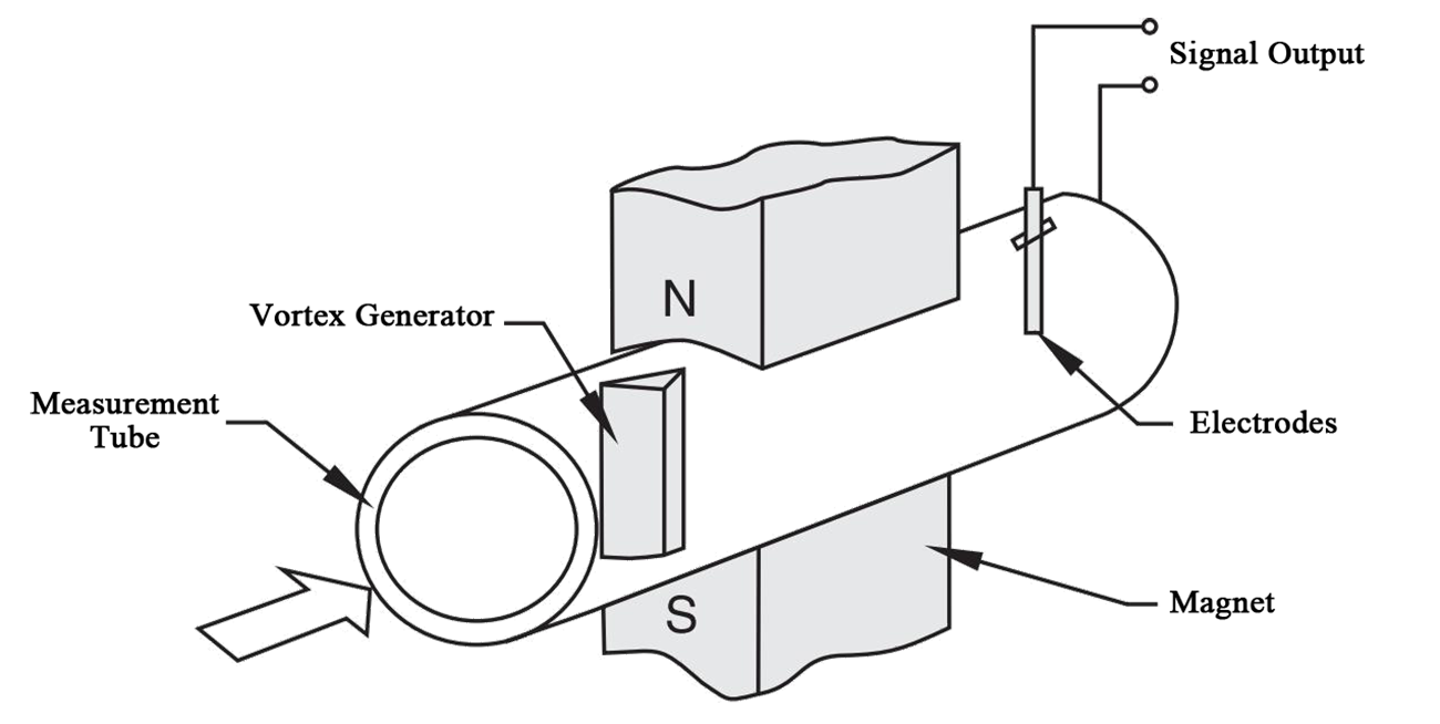
The operating principle is illustrated in Figure 1.
The bluff body is mounted within the measuring pipe. An insulated electrode rod is installed at a specified distance downstream of the generator, with a pair of permanent magnets vertically aligned between the generator and electrode.
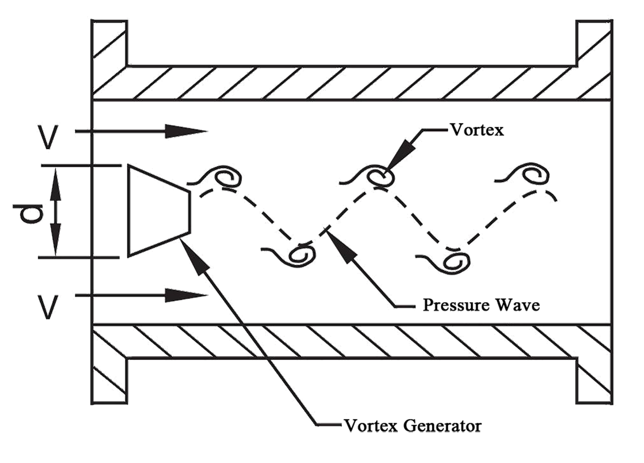
When fluid flows past the bluff body at velocity V, alternating vortices are produced on both sides of the generator, forming a “vortex street” (Figure 2). These vortices intersect the magnetic flux lines perpendicularly, generating periodic induced potential pulses. Within defined Reynolds number ranges, the vortex shedding frequency f on a single side exhibits linear proportionality to the fluid velocity V, as defined by the following formula:
f=St·V/d
Where:
V: Fluid velocity on both sides of the generator (m/s).
d: Characteristic width of the bluff body’s flow-facing surface (m).
St: Strouhal number, a constant within specific Reynolds number ranges for a given bluff body geometry.
With fixed pipeline and generator geometry, the flow rate QV becomes directly proportional to frequency f. The weak frequency-dependent signals are amplified, shaped, and processed via microprocessor to generate display readings and standardized outputs (e.g., 4–20 mA).
|
|
|
|
Figure 1 Vortex Flowmeter Structure Schematic
|
Figure 2 bluff body Schematic
|
Gas Vortex Flow Meter Selection
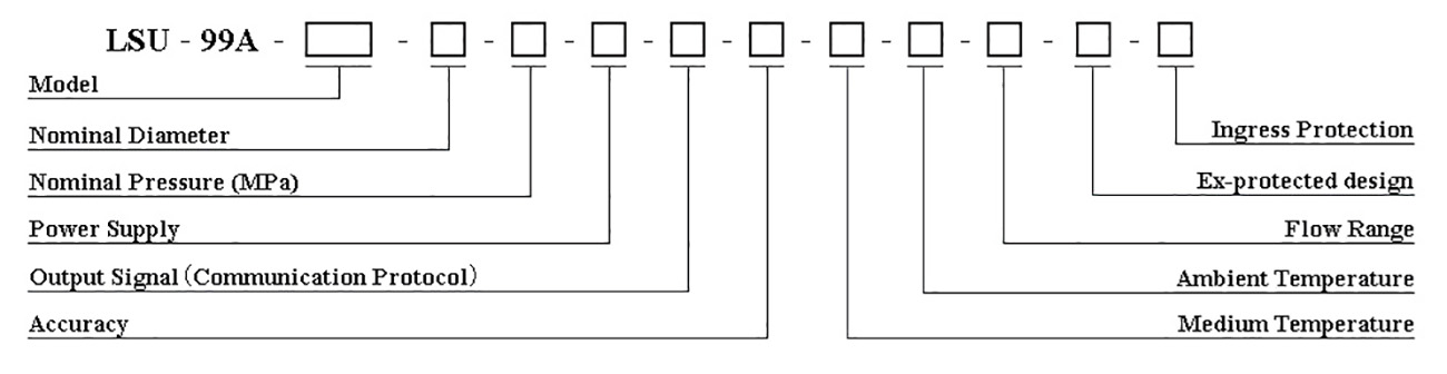
Model Coding:
Overview:
The Low Pressure Gas Vortex Flow Meter LSU-99A-DA features stable metering, high accuracy, long service life, and easy maintenance. As a new-generation flowmeter specifically developed for clean water and wastewater flow measurement at oilfield water injection stations and wellheads, it can operate in locations without power supply and serves as a direct replacement for conventional water meters.
Features:
1.Electrodes and piezoelectric crystal probes offer low resistance to liquids, reliable performance, and a long service life.
2.The flow meter core is detachable, facilitating convenient calibration and maintenance of the instrument.
3.Outputs pulse signals proportional to flow rate with no zero drift.
4.Features integrated temperature and pressure compensation.
5.Low pressure loss, suitable for metering sandy sewage and clean water.
6.The LCD displays instantaneous flow, cumulative flow, and allows daily water injection volume to be queried.
Specification:
|
Nominal Diameter
|
DN15~DN300
|
|
Nominal Pressure
|
1.0MPa~4.0MPa
|
|
Ingress Protection
|
IP65
|
|
Suitable Media
|
Water, Wastewater, Gas
|
|
Turndown Ratio
|
1:10, 1:15, 1:20
|
|
Accuracy
|
±0.75%, ±1.0%, ±1.5%
|
|
Medium Temperature
|
Liquid 0~70℃, 0~150℃;Gas 150℃~350℃
|
|
Ex-protected design
|
Ex d ⅡC T4 Gb, Ex ia ⅡC T4
|
|
Output Signal
|
Pulse/Frequency 5kHz, 4~20mA, 4~20mA+HART, RS485, MODBUS
|
|
Electrical Interface
|
M20×1.5 Internal Thread (M18×1.5 Internal Thread, 1/2NPT Internal Thread, are customizable)
|
|
Power Supply
|
AC220V, DC24V, DC3.6V (3+ years life, local display only, no output)
|
|
Ambient Temperature
|
-40℃~80℃ (requires protective measures below this threshold)
|
|
Ambient Humidity
|
5%~95%
|
Note: The instrument flanges comply with GB/T 9115-2010. For special requirements, the applicable standard must be specified (ASME B16.5-2009 Pipe Flanges and Flanged Fittings or the Ministry of Chemical Industry standard HG/T 20615-2009 Steel Pipe Flanges (Class Series)).
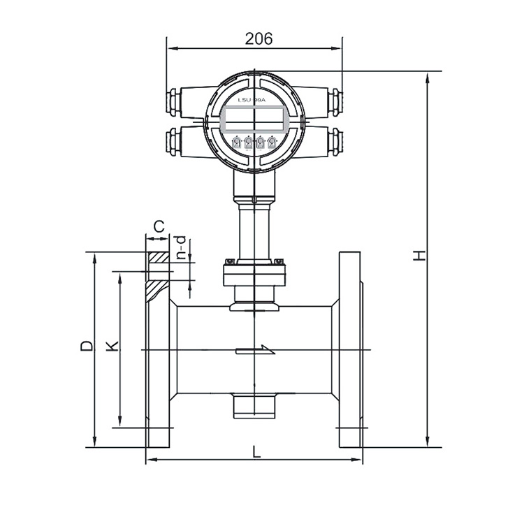
Installation Size:
|

|
|
|
Nominal Diameter
|
Nominal Pressure (MPa)
|
Normal flow range
|
Low flow range
|
L
|
H
|
D
|
K
|
n-d
|
C
|
|
DN25
|
4.0
|
0.7~7m³/h
|
0.4~4m³/h
|
150
|
320
|
115
|
85
|
4-Φ14
|
16
|
|
DN32
|
4.0
|
1.2~12m³/h
|
0.6~12m³/h
|
200
|
340
|
140
|
100
|
4-Φ18
|
18
|
|
DN40
|
4.0
|
1.8~18m³/h
|
0.7~14m³/h
|
200
|
350
|
150
|
110
|
4-Φ18
|
18
|
|
DN50
|
4.0
|
2.8~28m³/h
|
0.8~16m³/h
|
200
|
360
|
165
|
125
|
4-Φ18
|
20
|
|
DN65
|
4.0
|
4.8~48m³/h
|
2.8~56m³/h
|
200
|
373
|
185
|
145
|
8-Φ18
|
22
|
|
DN80
|
1.6
|
9.0~90m³/h
|
4.8~48m³/h
|
220
|
390
|
200
|
160
|
8-Φ18
|
20
|
|
4.0
|
24
|
|
DN100
|
1.6
|
14~140m³/h
|
9~90m³/h
|
250
|
400
|
220
|
180
|
8-Φ18
|
22
|
|
4.0
|
410
|
235
|
190
|
8-Φ22
|
26
|
|
DN150
|
1.6
|
32~320m³/h
|
14~140m³/h
|
300
|
473
|
285
|
240
|
8-Φ22
|
24
|
|
320
|
480
|
300
|
250
|
8-Φ26
|
30
|
|
DN200
|
1.0
|
56~560m³/h
|
32~320m³/h
|
320
|
525
|
340
|
295
|
8-Φ22
|
24
|
|
1.6
|
12-Φ22
|
26
|
|
2.5
|
350
|
535
|
360
|
310
|
12-Φ26
|
32
|
|
4.0
|
542
|
375
|
320
|
12-Φ30
|
36
|
|
DN250
|
1.0
|
88~700m³/h
|
56~560m³/h
|
400
|
560
|
395
|
350
|
12-Φ22
|
26
|
|
1.6
|
565
|
405
|
355
|
12-Φ26
|
28
|
|
2.5
|
575
|
425
|
370
|
12-Φ30
|
35
|
|
4.0
|
588
|
450
|
380
|
12-Φ33
|
42
|
|
DN300
|
1.0
|
128~1000m³/h
|
88~700m³/h
|
450
|
602
|
445
|
400
|
12-Φ22
|
28
|
|
1.6
|
610
|
460
|
410
|
12-Φ26
|
32
|
|
2.5
|
622
|
485
|
430
|
16-Φ30
|
38
|
|
4.0
|
637
|
515
|
450
|
16-Φ33
|
48
|