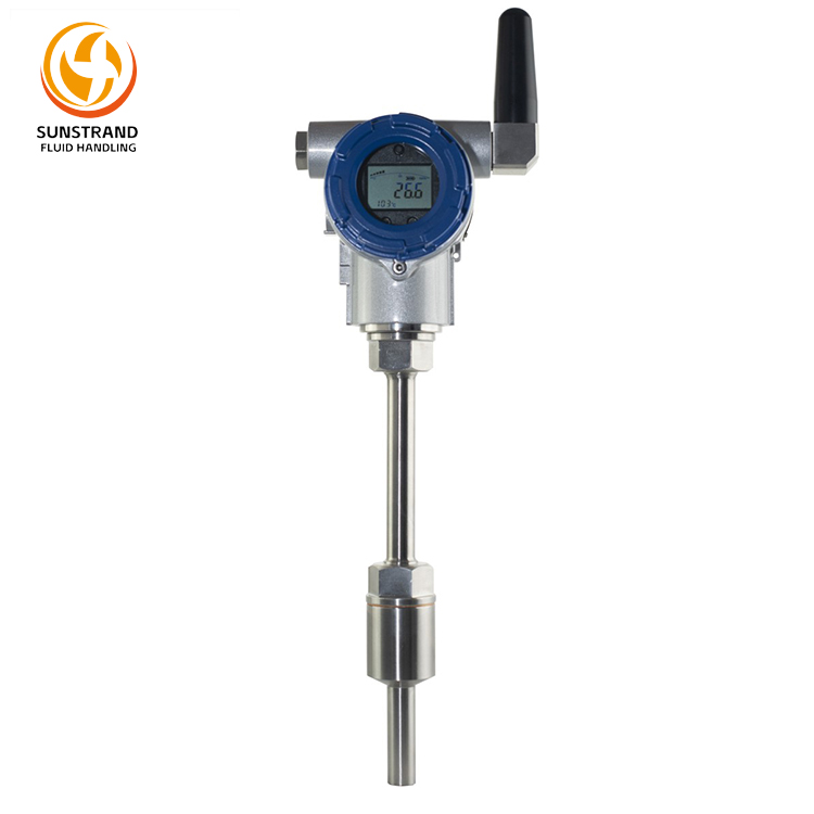
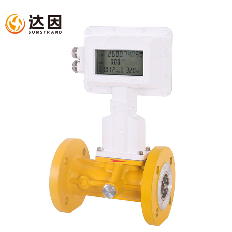
The LDQ-98A Series Electromagnetic Flow Meter is a velocity-type instrument based on Faraday’s Law of Electromagnetic Induction, designed to measure the volumetric flow rate of conductive media in pipelines. It consists of two main components: an electromagnetic flow sensor and a converter. This series is capable of measuring clean water, wastewater, corrosive media (e.g., acids, alkalis, and salts), and slurry-type conductive liquids.
The converter employs microcontroller-based embedded technology to achieves digital excitation and provides real-time parameters display (including instantaneous flow, cumulative flow, flow velocity, and flow percentage). Additionally, it supports multiple signal outputs such as frequency, current, and wired/wireless communication, enabling remote monitoring and measurement of flow data.
This product series features stable measurement, high accuracy, and long service life, making it widely applicable in petrochemical, petroleum, water supply and drainage, water injection, and chemical dosing systems.
Measurement Principle:Faraday’s Law of Electromagnetic Induction.
When a conductive liquid moves through a magnetic field and cuts the magnetic lines of flux, it generates an induced electromotive force (EMF), expressed as:
EMF=KBVD
Where:
K: Instrument constant
B: Magnetic flux density
V: Average flow velocity within the measuring tube
D: Inner diameter of the measuring tube
During flow measurement, the fluid passes through a magnetic field perpendicular to the flow direction. The conductive liquid induces a voltage proportional to the average flow velocity (i.e., volumetric flow rate). Therefore, the measured liquid must have a minimum conductivity (>5μS/cm). The induced voltage signal is detected by two electrodes in direct contact with the liquid, transmitted via cable to an amplifier, and converted into a standardized output signal.
Key Advantages of This Measurement Method:
1.The measurement tube contains no flow-obstructing internals, effectively eliminating ancillary pressure losses.
2.Since the measurement result is independent of physical parameters such as liquid pressure, temperature, density, viscosity, and conductivity (>5μS/cm), and the sensor signal is an electromotive force (EMF) that maintains an exact linear relationship with average flow velocity, the measurement demonstrates high accuracy and reliable operation.
3.Since the signal is generated within the fully magnetized space and represents an average value across the pipe cross-section, the sensor requires relatively short straight pipe sections, specifically 5 times the nominal pipe diameter (5DN).
4.As only the pipeline and electrodes of the electromagnetic flowmeter come into contact with the measured liquid, corrosion and wear resistance requirements can be met by appropriately selecting electrode and pipeline lining materials.
Electromagnetic Flow Meter Selection
Model Coding:

| Electromagnetic Flowmeter Model Selection Code Cross-Reference Table |
| A |
Product Type |
1—LDQ-98A-D |
| 2—LDQ-98A-W |
| 3—LDQ-98A-P |
| 4—LDQ-98A-G |
| 5—LDQ-98A-T |
| B |
Installation Method |
Y—Integrated Installation |
| F—Split Installation |
| C |
Sensor Diameter |
10—010 |
50—050 |
200—200 |
500—500 |
1000—102 |
| 15—015 |
65—065 |
250—250 |
600—600 |
1200—122 |
| 20—020 |
80—080 |
300—300 |
700—700 |
1400—142 |
| 25—025 |
100—100 |
350—350 |
800—800 |
1600—162 |
| 32—032 |
125—125 |
400—400 |
900—900 |
1800—182 |
| 40—040 |
150—150 |
450—450 |
|
2000—202 |
| D |
Electrode Material |
A—316L Stainless Steel |
| B—Hc |
| C—Hb |
| D—Ti |
| E—Ta |
| F—Pt |
| E |
Lining Material |
A—Polytetrafluoroethylene (PTFE, F4) |
| B—Fluorinated Ethylene Propylene (FEP, F46) |
| C—Ceramic |
| D—Chloroprene Rubber (CR) |
| E—Polyurethane (PU) |
| F—Fluoroplastic (FS) |
| F |
Medium Temperature |
1—≤100℃ |
| 2—≤120℃ |
| 3—≤180℃ |
| 4—≤65℃ |
| 5—≤80℃ |
| 6—≤60℃ |
| G |
Power Supply |
1—220VAC |
| 2—24VDC |
| 3—3.6VDC |
| H |
Ambient Temperature |
1—-10℃~45℃ |
| 2—-20℃~55℃ |
| 3—-30℃~80℃ |
| I |
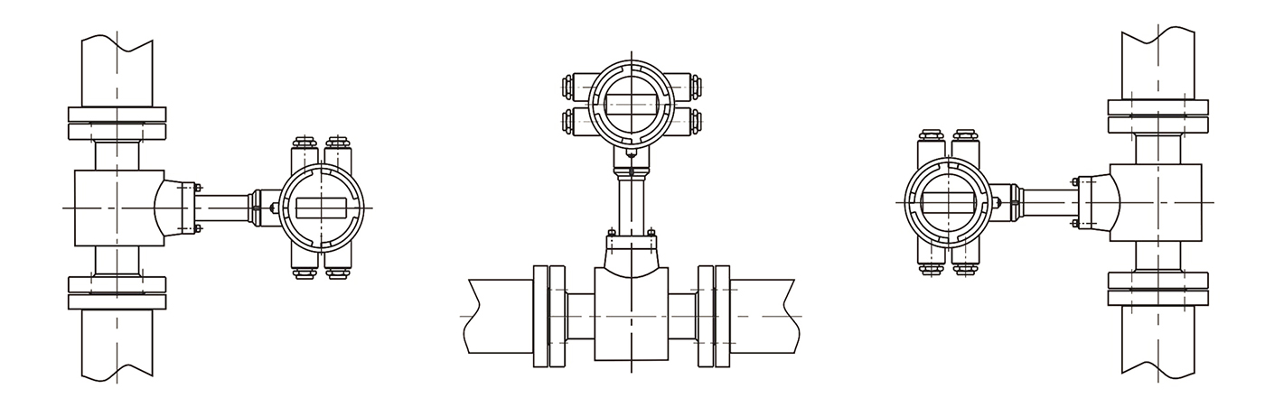
Converter Installation Orientation |
A—Type A |
| B—Type B |
| C—Type C |
| J |
Output Signal |
1—Frequency 5000Hz 4~20mA(+HRAT) |
2—Frequency 5000Hz 4~20mA
RS485/MODBUS |
| 3—Frequency 5000Hz 4~20mA Other communication standards can be agreed upon |
| K |
Grounding Ring |
0—No Grounding Ring |
| 1—Grounding Ring |
| 2—Wrapped Grounding Ring |
| L |
Ingress Protection |
1—IP 54 |
| 2—IP 65 |
| 3—IP 67 |
| 4—IP 68 |
| M |
Ex-protected design |
O—Standard Type |
| E—Explosion-proof Type |
| N |
Nominal Pressure(MPa) |
Directly enter the Nominal Pressure value |
| O |
Flow Range |
Directly enter the minimum and maximum values |
| A—Horizontal |
B—Vertical Left |
C—Vertical Right |
 |
Overview:
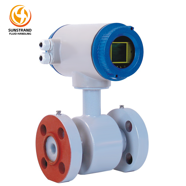
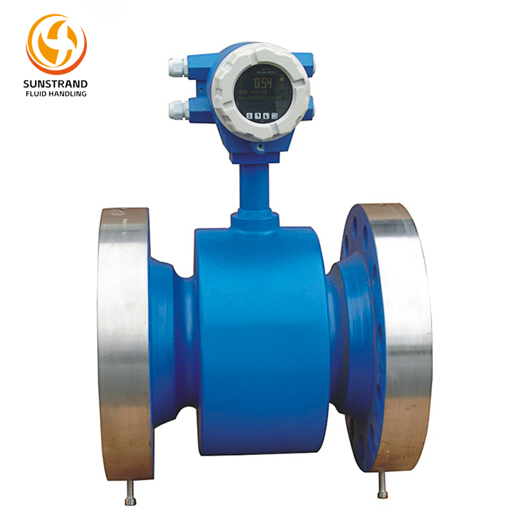
Medium Pressure Electromagnetic Flow Meter LDQ-98A-P is a product specifically developed for high-pressure flow measurement of various liquids in oil fields. It is designed for metering pulsating flows of molecular and polymer liquids in polymer mother liquor. This product features stable measurement, high accuracy, and long service life. It is widely applied in petrochemical, petroleum, water supply and drainage, water injection, and chemical dosing systems.
Features:
1.Accurate operation starting from a flow rate of 0.01 m³/h.
2.Capable of measuring liquids with particles, slurries, ore slurries, and similar media.
3.Accurately meters various liquids and chemical additives in plunger pumps.
4.Superior anti-interference performance: Resists static electricity and lightning surge voltages ≥1500 V.
5.Robust construction, enhanced safety, and aesthetic design make it suitable for medium-to-high pressure applications.
Specification:
| Nominal Diameter |
DN10~DN200 |
| Nominal Pressure |
6.3MPa~16MPa |
| Ingress Protection |
IP68 (Sensor), IP65 (Converter) |
| Electrode Material |
316L Stainless Steel, Hastelloy C, Hastelloy B, Ti, Ta, Pt |
| Suitable Media |
Water, Wastewater, Polymers, Acid/Alkali Solutions, Corrosives, Pulp, Slurry |
| Medium Conductivity |
>5μS/cm |
| Turndown Ratio |
10 :1, 20:1, 30:1 |
| Accuracy |
± 0.5%, ±1.0% |
| Lining Material |
PTFE (F4) |
FEP (F46) |
| Applicable Diameter |
DN10~DN200 |
DN10~DN200 |
| Medium Temperature |
≤100℃ |
≤120℃ |
| Converter Model |
DS08 |
| Ex-protected design |
Ex d ib mb IIC T5 Gb |
| Output Signal |
Pulse/Frequency 5kHz,4~20mA,4~20mA+HART,RS485(Modbus RTU) |
| Electrical Interface |
M20×1.5 Internal Thread (M18×1.5 Internal Thread, 1/2NPT Internal Thread, are customizable) |
| Power Supply |
Built-in 3.6V Li-battery (3+ years life, local display only, no output), AC220V±10% 50Hz, DC24V±5% |
| Ambient Temperature |
-30℃~80℃ (requires protective measures below this threshold) |
| Ambient Humidity |
5%~95% |
Note: The instrument flanges comply with GB/T 9115-2010. For special requirements, the applicable standard must be specified (ASME B16.5-2009 Pipe Flanges and Flanged Fittings or the Ministry of Chemical Industry standard HG/T 20615-2009 Steel Pipe Flanges (Class Series)).
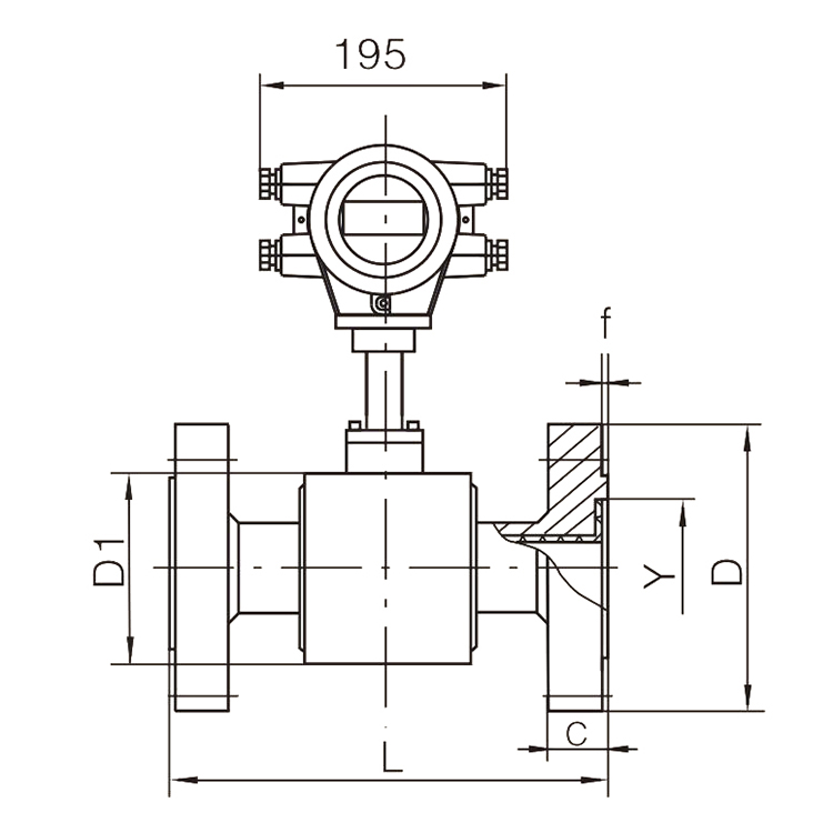
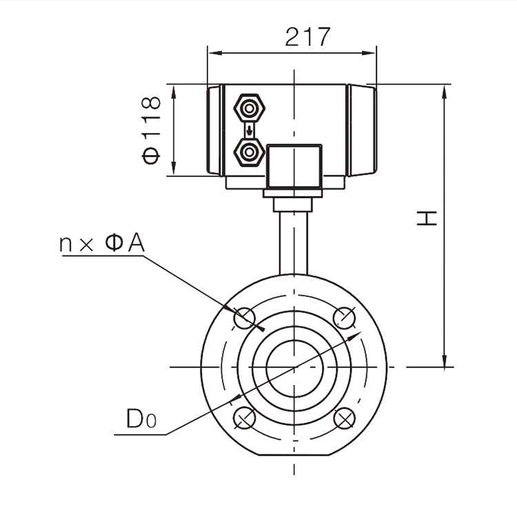
Installation Size:
| Nominal Diameter(mm) |
Flow Range (m³/h) |
Nominal Pressure (MPa) |
Overall Dimensions(mm) |
Flange Dimensions(mm) |
| L |
H |
D1 |
D |
D0 |
n×A |
Y |
f |
C |
| 10 |
0.1~2 |
6.3、10、16 |
200 |
300 |
98 |
100 |
70 |
4×14 |
35 |
4 |
20 |
| 15 |
0.2~4 |
6.3、10、16 |
200 |
310 |
120 |
105 |
75 |
4×14 |
40 |
4 |
20 |
| 20 |
0.2~4
0.35~7 |
6.3、10 |
200 |
310 |
120 |
130 |
90 |
4×18 |
51 |
4 |
22 |
| 16 |
200 |
310 |
120 |
130 |
90 |
4×18 |
51 |
4 |
24 |
| 25 |
0.55~11 |
6.3、10、16 |
220 |
315 |
130 |
140 |
100 |
4×18 |
58 |
4 |
24 |
| 32 |
0.55~11
1~20 |
6.3、10 |
220 |
320 |
138 |
155 |
110 |
4×22 |
66 |
4 |
24 |
| 16 |
230 |
320 |
138 |
155 |
110 |
4×22 |
66 |
4 |
28 |
| 40 |
1~20
1.5~30 |
6.3,10 |
220 |
323 |
146 |
170 |
125 |
4×22 |
76 |
4 |
26 |
| 16 |
230 |
323 |
146 |
170 |
125 |
4×22 |
76 |
4 |
28 |
| 50 |
0.55~11
1~20
2.5~50 |
6.3 |
220 |
329 |
158 |
180 |
135 |
4×22 |
88 |
4 |
26 |
| 10 |
220 |
329 |
158 |
195 |
145 |
4×26 |
88 |
4 |
28 |
| 16 |
240 |
329 |
158 |
195 |
145 |
4×26 |
88 |
4 |
30 |
| 65 |
1.5~30
2.5~50
4~80 |
6.3 |
220 |
333 |
166 |
205 |
160 |
8×22 |
110 |
4 |
26 |
| 10 |
240 |
333 |
166 |
220 |
170 |
8×26 |
110 |
4 |
30 |
| 16 |
260 |
333 |
166 |
220 |
170 |
8×26 |
110 |
4 |
34 |
| 80 |
5.5~110 |
6.3 |
240 |
348 |
196 |
215 |
170 |
8×22 |
121 |
4 |
28 |
| 10 |
240 |
348 |
196 |
230 |
180 |
8×26 |
121 |
4 |
32 |
| 16 |
280 |
348 |
196 |
230 |
180 |
8×26 |
121 |
4 |
36 |
| 100 |
7~140
8.5~170 |
6.3 |
280 |
350 |
200 |
250 |
200 |
8×26 |
150 |
4.5 |
30 |
| 10 |
300 |
350 |
200 |
265 |
210 |
8×30 |
150 |
4.5 |
36 |
| 16 |
300 |
350 |
200 |
265 |
210 |
8×30 |
150 |
4.5 |
40 |
| 125 |
12~240
14~280 |
6.3 |
280 |
363 |
226 |
295 |
240 |
8×30 |
176 |
4.5 |
34 |
| 10 |
300 |
363 |
226 |
315 |
250 |
8×33 |
176 |
4.5 |
40 |
| 16 |
350 |
363 |
226 |
315 |
250 |
8×33 |
176 |
4.5 |
44 |
| 150 |
16~320
20~400 |
6.3 |
350 |
370 |
240 |
345 |
280 |
8×33 |
204 |
4.5 |
36 |
| 10 |
350 |
370 |
240 |
355 |
290 |
12×33 |
204 |
4.5 |
44 |
| 16 |
400 |
370 |
240 |
355 |
290 |
12×33 |
204 |
4.5 |
50 |
| 200 |
28~560
35~700 |
6.3 |
400 |
400 |
300 |
415 |
345 |
12×36 |
260 |
4.5 |
42 |
| 10 |
400 |
400 |
300 |
430 |
360 |
12×36 |
260 |
4.5 |
52 |
| 16 |
420 |
400 |
300 |
430 |
360 |
12×36 |
260 |
4.5 |
60 |