Warning: mysqli_query(): (HY000/1032): Can't find record in 'wp_options' in /www/wwwroot/dayin.junj.cc/wp-includes/class-wpdb.php on line 2351 ALS Smart Vortex Precession In Line Flow Meter | Sunstrand
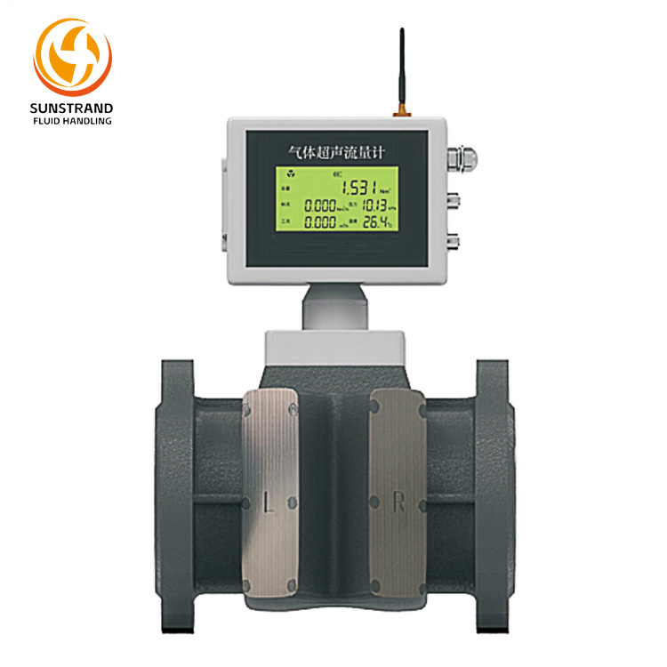
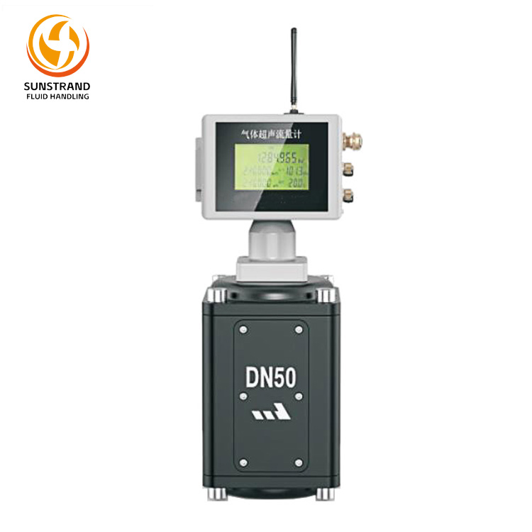
The ALS Smart Vortex Precession Flow Meter is a flow meter that directly displays the medium’s volumetric flow under standard conditions (Po=101.325kPa, To=293.15K). It achieves standard flow measurement for gas mediums flow meter by detecting corresponding parameters through its internal temperature sensor, pressure sensor, and flow sensor. It is widely applicable for gas metering in petroleum, chemical, metallurgy, and urban gas distribution pipeline networks.
The ALS Smart Vortex Precession Flow Meter is a flow meter that directly displays the medium’s volumetric flow under standard conditions (Po=101.325kPa, To=293.15K). It achieves standard flow measurement for gas mediums flow meter by detecting corresponding parameters through its internal temperature sensor, pressure sensor, and flow sensor. It is widely applicable for gas metering in petroleum, chemical, metallurgy, and urban gas distribution pipeline networks.
Measurement Principle:
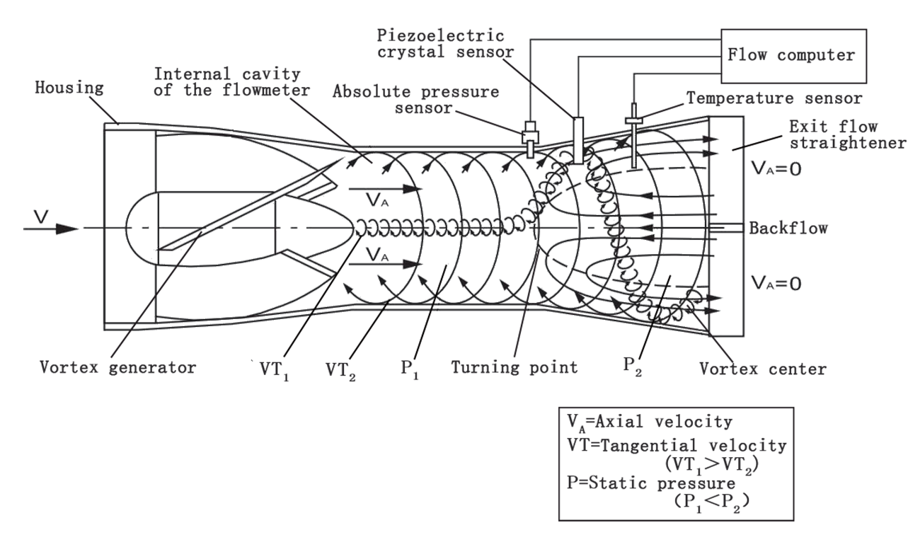
When axial fluid enters the flow sensor inlet, the swirl generator forces it to rotate around the centerline, creating a vortex flow. This vortex flow precesses within the Venturi tube. Upon reaching the contraction section, the sudden constriction accelerates the vortex. As the flow passes through the diffuser section, the vortex core precesses along a conical helical path.
At this point, the precession frequency of the vortex core passing the detection point is proportional to the fluid’s flow velocity. The precession frequency signal of the vortex flow, detected by the piezoelectric sensor, undergoes amplification, filtering, and shaping processing in the pre-amplifier circuit to remove external interference signals. This processed signal is then converted into a pulse signal proportional to the fluid velocity. Together with the temperature and pressure signals detected by the pressure sensor and temperature sensor, these signals are fed into the display instrument for computational processing.
Technical Parameters
Features:
1.Integrates pressure, temperature, and flow sensors into a single unit. The specially designed flow sensor enhances shock and interference resistance.
2.Lower straight pipe run requirements (5DN upstream, 3DN downstream) save installation costs.
3.Ultra-low power consumption, with a built-in lithium battery providing a service life of up to 5 years.
4.Employs E2PROM data storage technology to securely store operational parameter data long-term.
5.The flow totalizer can be rotated 180° for convenient installation in different Procedures.
6.Utilizes advanced dual-probe vortex precession flow sensor technology, featuring: strong anti-interference capability; high accuracy; no mechanical moving parts; corrosion resistance; compact structure; high reliability; excellent stability; and minimal maintenance requirements.
Built-in 3.6V Li-battery (5 years life, local display only, no output), DC24V±10%
Ambient Temperature
-30℃~60℃ (requires protective measures below this threshold)
Converter Model
5%~95%
Note: The instrument flanges comply with GB/9113-2010. For special requirements, the applicable standard must be specified (ASME B16.5-2009 Pipe Flanges and Flanged Fittings or the Ministry of Chemical Industry standard HG/T 20615-2009 Steel Pipe Flanges (Class Series))
Installation Size:
Model
Nominal Diameter
Nominal Pressure
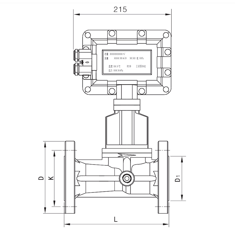
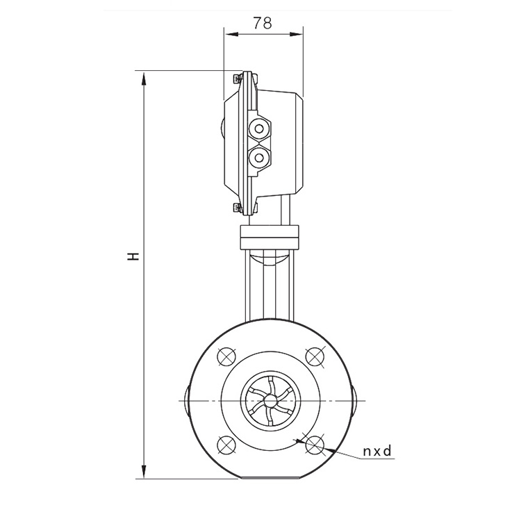
Overall Dimensions(mm)
Flange Dimensions(mm)
L
H
D
K
n×d
D1
ALS-20
DN20
PN16~PN40
180
347
115
75
4×14
58
PN63
352
130
90
4×18
58
ALS-25A/B
DN25
PN16~PN40
180
347
115
85
4×14
68
PN63
355
140
100
4×18
68
ALS-32A/B
DN32
PN16~PN40
200
362
140
100
4×18
78
PN63
370
155
110
4×22
78
ALS-50A/B
DN50
PN16~PN40
230
405
165
125
4×18
102
PN63
410
180
135
4×22
102
ALS-80A/B
DN80
PN16~PN40
330
428
200
160
4×18
138
PN63
435
215
170
8×22
138
ALS-100A/B
DN100
PN10~PN16
410
446
220
180
8×18
158
PN25~PN40
446
235
190
8×22
162
PN63
460
250
200
8×26
162
ALS-150A/B
DN150
PN10~PN16
580
509
285
240
8×22
212
PN25~PN40
509
300
250
8×26
218
PN63
540
345
280
8×33
218
ALS-200A/B
DN200
PN10~PN16
700
560
340
295
12×22
268
PN25
560
360
310
12×26
278
PN40
560
375
320
12×30
285
ALS-200A/B
DN200
PN63
700
587
415
345
12×36
285
Vortex Precession Flow Meter Selection
Model Coding:
Vortex Precession Flow Meter Model Selection Code Cross-Reference Table
A
Nominal Diameter
20—DN20
80—DN80
25—DN25
100—DN100
32—DN32
150—DN150
50—DN50
200—DN200
B
Nominal Pressure
16—PN16
63—PN63
25—PN25
100—PN100
40—PN40
C
Body Material
1—Cast Aluminum
2—304 Stainless Steel
3—Carbon Steel
D
Output Signal
1—Frequency (local display)
2—Frequency
4~20mA
3—Frequency
4~20mA
RS485/MODBUS
4—Frequency
4~20mA (+HART)
5—With Wireless Module
E
Medium Temperature
1—-20℃~+60℃
1—-20℃~+80℃
F
Installation Site
1—Indoor,
2—Outdoor
3—Outdoor with protective enclosure
4—Outdoor with insulated enclosure
G
Temperature And Pressure Compensation
1—Standard Type (without compensation)
2—Smart Type (with temperature and pressure compensation)
H
Filled In Directly
□ Flow Range
□ Accuracy
□ Ambient Temperature
□ Power Supply
□ Ex-protected Design
□ Ingress Protection
WE ARE HERE TO SUPPORT YOU!
Further information or a personal consultation? Our products and know-how
are there to provide solutions.