
A misconfigured differential pressure transmitter doesn’t just produce bad numbers — it can trigger false alarms, disrupt process control, and cost your facility days of unplanned downtime. For engineers and procurement teams selecting and deploying instrumentation at scale, understanding how to install a differential pressure transmitter step-by-step is not optional knowledge. It is operational discipline.
This guide covers every stage of a correct differential pressure transmitter installation: pre-installation verification, mounting the transmitter in the right orientation, connecting impulse lines to the correct pressure sides, electrical wiring, and final zero calibration. Follow these steps and your transmitter will deliver stable, accurate measurements from commissioning day forward.
A differential pressure transmitter measures the difference in pressure between two process points and converts it into a standardized output signal — typically 4–20 mA with HART. It is one of the most widely deployed instruments in industrial facilities, used for flow measurement across orifice plates, liquid level detection in pressurized vessels, and filter condition monitoring.
Because the device measures a difference rather than an absolute value, any asymmetry in the installation — a trapped air bubble on the liquid side, an incorrect high/low pressure connection, or a misaligned mounting bracket — introduces a systematic measurement error that calibration alone cannot correct. Getting the physical installation right is the foundation of everything.
Learn More: Differential Pressure Transmitters Explained
Rushing into installation without proper preparation is the single most common cause of rework. Before touching the transmitter, complete the following checks:
| Item | Purpose |
|---|---|
| Adjustable wrenches & tube benders | Impulse line routing and connection |
| PTFE tape / thread sealant | Sealing threaded process connections |
| Compression fittings (e.g. Swagelok) | Leak-free tubing connections |
| Multimeter / loop calibrator | Wiring verification and signal check |
| HART handheld communicator | Configuration and zero trim |
| Soapy water or leak detection spray | Post-installation leak check |
| PPE (gloves, safety glasses) | Personnel protection |
Before any mechanical work begins, isolate the process line and apply LOTO to both the process isolation valves and the electrical supply. Confirm zero energy state with a pressure gauge before proceeding.
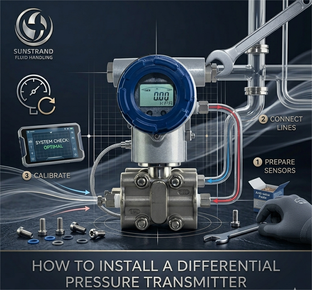
Mounting the transmitter in the right position relative to the process taps is the most critical physical decision you will make. The rule is governed by the nature of your process fluid:
| Process Fluid | Transmitter Position | Tube Slope Direction | Key Risk if Wrong |
|---|---|---|---|
| Liquid | Below taps | Down toward transmitter | Trapped gas → reading too low |
| Gas / Vapor | Above taps | Down toward process pipe | Accumulated liquid → reading too high |
| Steam | Below condensate pots | Down toward transmitter | Unequal condensate legs → offset error |
Additional considerations: avoid locations with strong vibration, direct sunlight, or extreme ambient temperature swings. In hazardous area classifications, confirm your transmitter’s ATEX/IECEx rating matches the zone before fixing the bracket.
Secure the mounting bracket to a 2-inch pipe stand or panel using the appropriate hardware. Most transmitters are designed for standard 2-inch pipe mounting via a bent or flat bracket.
A valve manifold is mandatory — not optional — for any differential pressure transmitter installation. It allows safe isolation, equalization, and venting during commissioning, maintenance, and zero calibration.
Mount the manifold directly to the transmitter’s process connection flanges to minimize dead-leg volume and reduce leak points.
This is the step where reversed connections most commonly occur, leading to negative differential readings or controller reversals in the DCS.
Identify the high pressure side and low pressure side before connecting anything:
Connect the high-pressure impulse line to the port marked “H” or “+” on the transmitter. Connect the low-pressure line to the port marked “L” or “−”. Do not rely on color coding alone — verify against your P&ID and instrument data sheet.
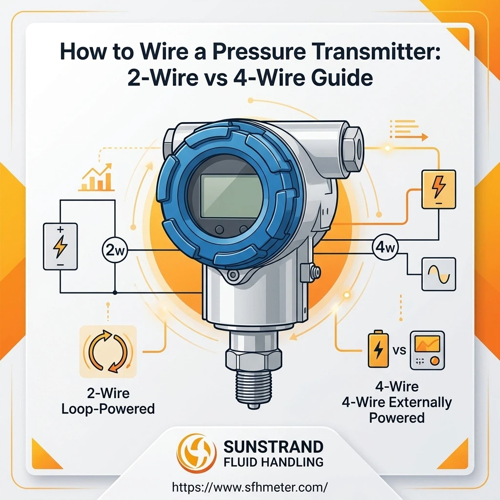
Remove the terminal compartment cover from the transmitter housing. Connect the positive (+) and negative (−) leads from your 24 VDC loop supply to the corresponding terminals.
Verify loop continuity with a multimeter before applying power. For HART-enabled transmitters, confirm the minimum loop resistance is within HART communication requirements (typically 230–600 Ω).
Before energizing the transmitter with live process pressure, perform a leak check on all mechanical connections:
A zero trim corrects for any offset caused by the transmitter’s physical mounting position relative to the process taps. This is the final and essential step of any differential pressure transmitter installation.
| Mistake | Consequence | Prevention |
|---|---|---|
| Transmitter above taps on liquid service | Trapped gas → sustained negative offset | Follow fluid-type mounting rules in Step 1 |
| H/L connections reversed | Negative or backward reading in DCS | Verify against P&ID before connecting |
| No zero trim after installation | Systematic offset error throughout operating range | Always perform zero trim with manifold equalized |
| Unequal impulse line lengths | Temperature-induced measurement drift | Route both legs parallel and equal length |
| Signal cable in same conduit as power | EMI noise on 4–20 mA loop | Separate conduits; use shielded cable |
| Over-torqued compression fittings | Collapsed ferrule → leak point | Finger-tight + 1¼ turns only |
What is the correct mounting orientation for a differential pressure transmitter on a liquid line?
Mount the transmitter below the process taps and slope the impulse tubing downward toward the transmitter. This ensures the impulse lines remain fully liquid-filled at all times, preventing gas pockets that would cause the transmitter to read lower than the actual process differential.
Why do I need a valve manifold? Can I connect the transmitter directly to the process taps?
A valve manifold is essential for safe commissioning, maintenance isolation, and zero calibration. Without one, you cannot apply equal pressure to both sides of the transmitter for zero trim, and you cannot isolate the instrument for maintenance without shutting down the process. Direct connection without a manifold is not considered an acceptable industrial practice.
How do I identify the high pressure side and low pressure side for a flow application?
For flow measurement across a primary element (orifice plate, venturi, or flow nozzle), the upstream tap — before the restriction — is always the high pressure side. The downstream tap is the low pressure side. Connect the upstream tap to the port marked “H” or “+” on the transmitter body and manifold.
What cable type should I use for differential pressure transmitter wiring?
Use shielded twisted-pair cable with a conductor cross-section between 0.5 mm² and 2.5 mm². Ground the shield at only one end (control room side) to prevent ground loops. Route signal cables in dedicated conduit, separated from 240V or 480V power cables.
What is a zero trim and when should I perform it?
A zero trim is a sensor calibration procedure that establishes the transmitter’s zero reference under conditions of true zero differential pressure (both sides equalized via the manifold’s equalizing valve). It compensates for offset caused by the physical mounting position. Always perform a zero trim after mechanical installation is complete and before putting the transmitter into service.
How often should a differential pressure transmitter be recalibrated after installation?
Industry practice for most process applications is annual calibration verification, typically during scheduled turnarounds or maintenance windows. High-accuracy metering applications (custody transfer, emissions monitoring) may require more frequent verification. Always follow your site’s instrument management program and the manufacturer’s recommended calibration interval.
Can I install a differential pressure transmitter on a steam line without condensate pots?
No. Condensate pots are required for steam applications. They create stable, cool water legs on both the high and low pressure sides, protecting the sensing diaphragm from high-temperature steam and ensuring the transmitter measures a stable, equal liquid reference on both legs. Without condensate pots, unequal steam condensation in the two impulse legs creates a varying, asymmetric offset.
What causes a differential pressure transmitter to read negative (below 4 mA) after installation?
A negative reading most commonly indicates either a reversed H/L connection (high and low pressure lines swapped) or that the transmitter’s zero trim was performed incorrectly. Verify that the high-pressure tap is connected to the “H” port. If connections are correct, check whether the transmitter is mounted above the taps on a liquid service, which would cause a gas-induced negative offset.
Is it possible to install a differential pressure transmitter in a hazardous area (classified zone)?
Yes, provided you select a transmitter model with the appropriate explosion protection certification for your area classification. Common certifications include ATEX (Europe) and IECEx (international). The certification must match the zone (Zone 1, Zone 2, Division 1, Division 2) and gas group of your hazardous area. Follow all associated installation requirements for certified equipment, including cable entry sealing and grounding.
What is the difference between a 3-valve manifold and a 5-valve manifold for differential pressure transmitters?
A 3-valve manifold has two block valves (one for each pressure side) and one equalizing valve between them — sufficient for most process applications. A 5-valve manifold adds two bleed/vent valves that allow each impulse leg to be vented to atmosphere independently. The 5-valve configuration is preferred in high-pressure services, hazardous fluid services, or anywhere the ability to individually vent each side for safe maintenance is operationally important.
Differential Pressure Transmitters Explained
Differential Pressure Transmitter Calibration Procedure
At Sunstrand, we supply differential pressure transmitters, manifolds, impulse tubing, and accessories engineered for the demands of oil & gas, chemical processing, power generation, and water treatment facilities. Our technical team works directly with procurement and engineering teams to select the right instrument for the application — not just any transmitter off a catalog page.
Whether you need a single replacement unit or specifications for a multi-site instrumentation rollout, we can support your project from selection through commissioning.
→ Request a Quote or Technical Consultation from Sunstrand
Have a specific application challenge — corrosive media, elevated temperature, remote seal requirements? Contact our engineering team and we will identify the right transmitter configuration for your process conditions.
This guide is intended for qualified instrumentation engineers and maintenance technicians. Always follow your facility’s safety management system, relevant national codes, and the specific installation instructions provided by the transmitter manufacturer.