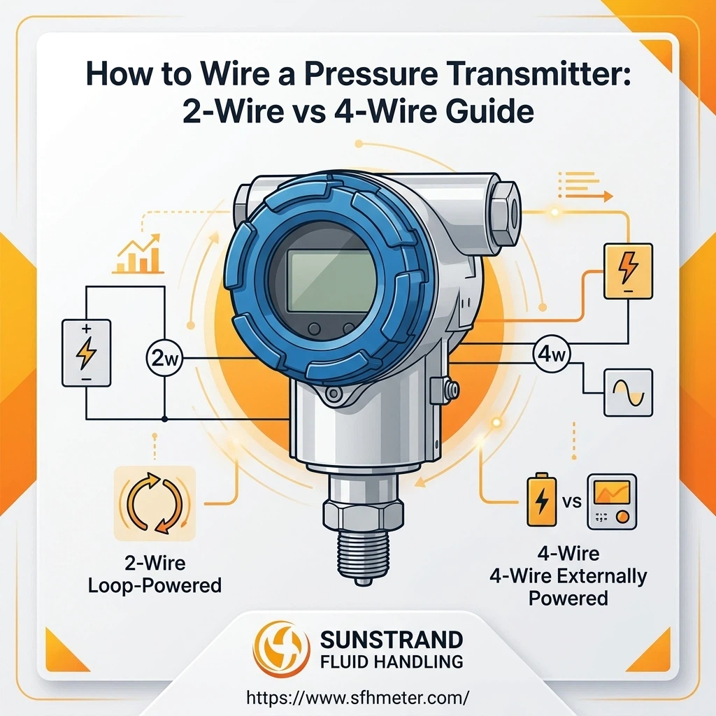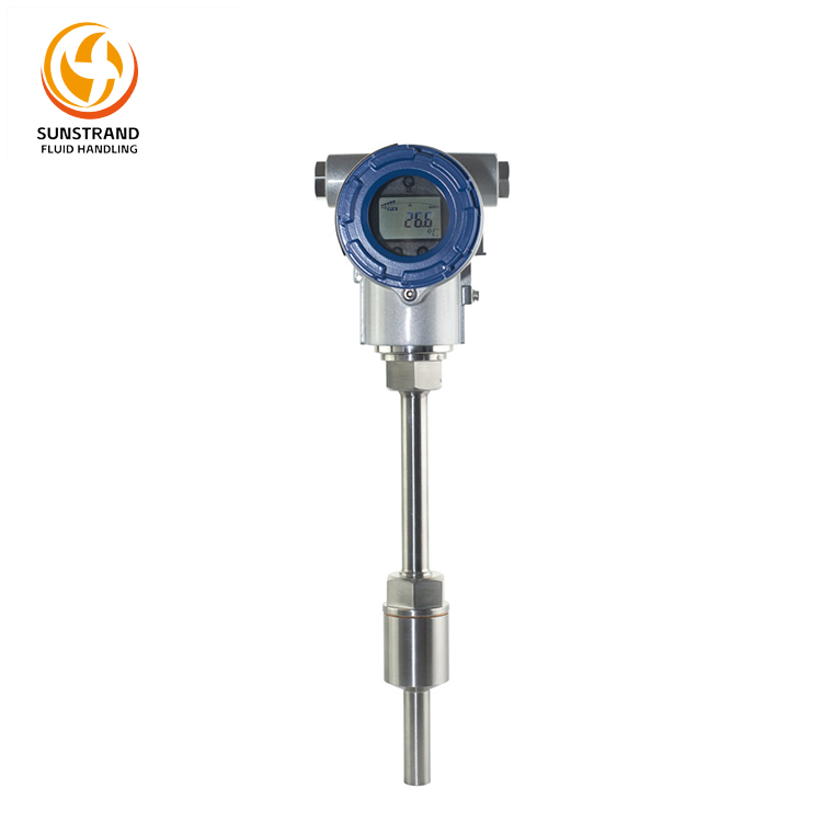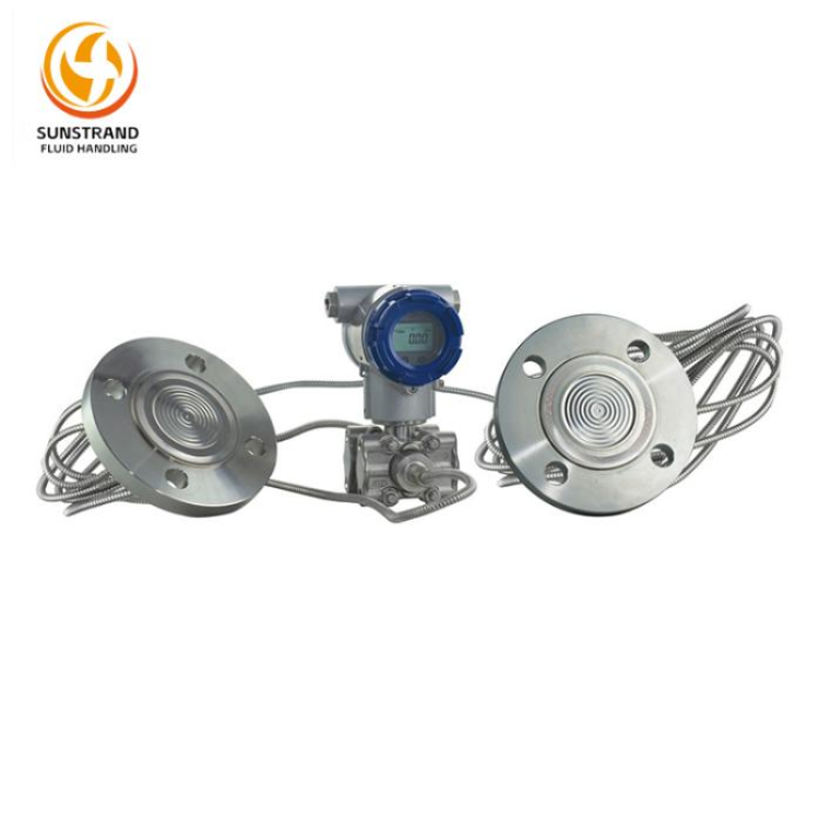

Accurate process measurement depends on one thing above all else: a properly calibrated instrument. Whether you are monitoring flow in a chemical plant or tracking level in a storage vessel, a faulty differential pressure transmitter can cascade into safety risks, product loss, and regulatory non-compliance. This guide from Sunstrand walks you through the complete differential pressure transmitter calibration procedure – the tools you need, the step-by-step process, and the expert tips that separate a good calibration from a great one.
A differential pressure transmitter measures the difference in pressure between two points in a process system and converts it into a proportional 4–20 mA output signal. This mA output travels to a PLC or DCS, where it is used to infer flow rate, liquid level, or filter condition.
Over time, every transmitter drifts. Mechanical stress from constant pressure fluctuations, aging of electronic components, and the effect of temperature fluctuations on sensor materials all cause the output of the transmitter to deviate from its true value. When that happens, every downstream calculation – flow totals, custody transfers, batch quantities – becomes unreliable.
Regular pressure transmitter calibration corrects that drift and restores measurement confidence. It also provides performance history that helps you decide whether to shorten or extend your calibration interval.
Before starting any transmitter calibration procedure, gather the following equipment and verify that every reference instrument is itself within its valid calibration date:
Sunstrand Tip: Your reference equipment should be at least three to four times more accurate than the transmitter being calibrated. A digital multimeter with ±0.05% accuracy is suitable for a transmitter rated at ±0.2% of span.
Taking a few minutes before the calibration starts prevents the most common errors:
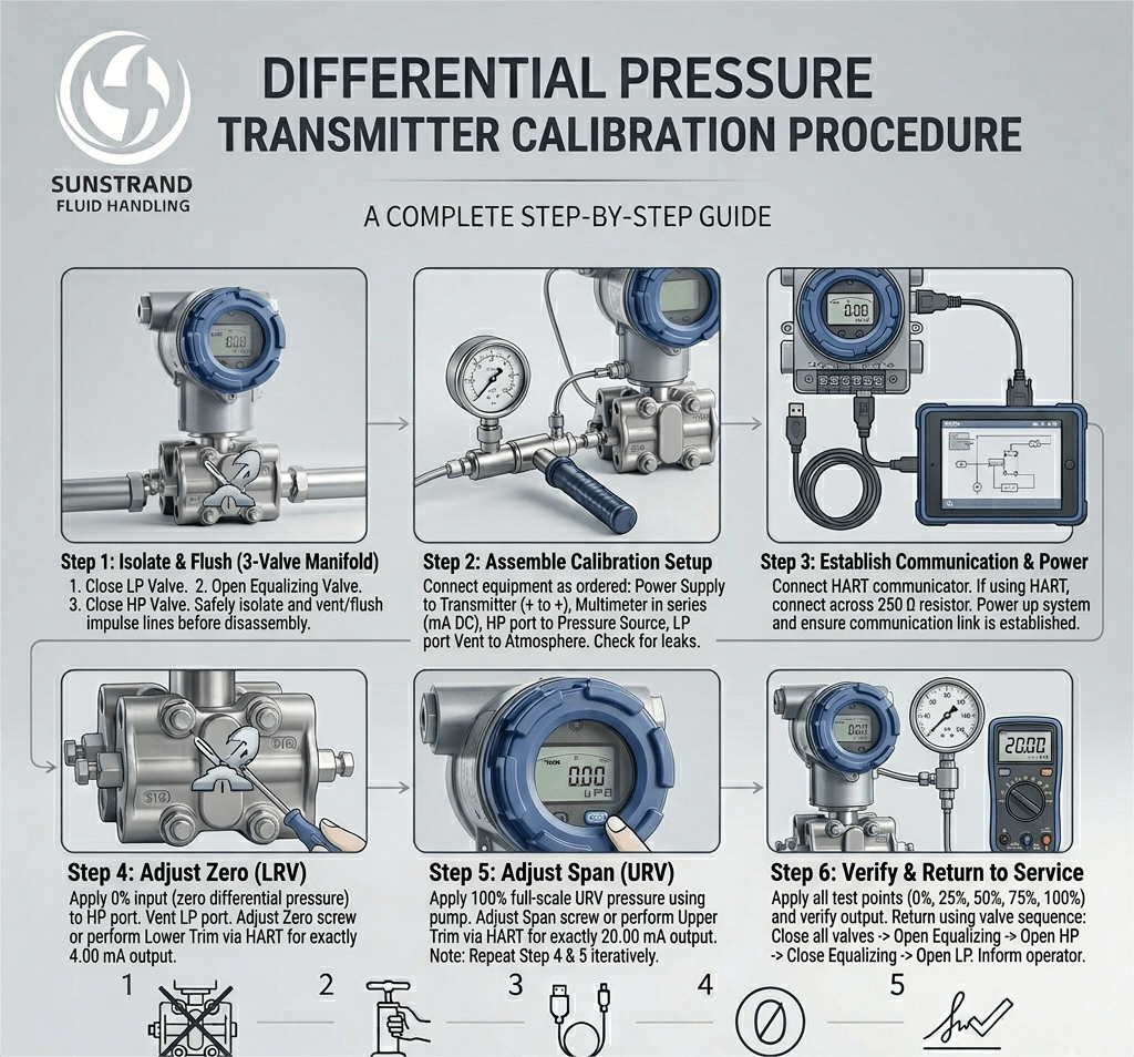
For a dp flow transmitter installed in a three-valve manifold configuration, follow this sequence:
The transmitter is now safely isolated. If the process medium is hazardous, flush the impulse lines to a closed drain before disconnecting any fittings.
Connect the equipment in the following order:
Double-check all connections for polarity and leak tightness before applying power.
Before making any adjustments, document the transmitter’s current condition. Apply each test-point pressure in ascending order (0%, 25%, 50%, 75%, 100%) and then in descending order, recording the actual mA output and the applied pressure at each point. This “As Found” dataset is critical for maintaining instrument performance history and for deciding whether recalibration is actually necessary.
Important: When approaching each test point, increase pressure slowly and steadily. Never overshoot a target pressure – hysteresis means a descending reading will not match an ascending one at the same point.
Because zero and span adjustments are interactive – changing span slightly shifts zero – repeat Steps 4 and 5 iteratively until both endpoints are within your acceptable tolerance.
With zero and span set, apply each calibration test point again and record the actual mA signals. Compare each reading against the expected values from your calibration table:
| Input % of Span | Applied Pressure | Expected mA | Acceptable Range |
|---|---|---|---|
| 0% | 0 (LRV) | 4.00 mA | 3.92 – 4.08 mA |
| 25% | 25% of span | 8.00 mA | 7.92 – 8.08 mA |
| 50% | 50% of span | 12.00 mA | 11.92 – 12.08 mA |
| 75% | 75% of span | 16.00 mA | 15.92 – 16.08 mA |
| 100% | URV | 20.00 mA | 19.92 – 20.08 mA |
If all readings fall within your plant’s maximum permissible error (MPE), the calibration is successful. Record these values as your “As Left” data.
With calibration confirmed, reconnect the transmitter to the process using the following valve sequence:
Verify the live reading in the DCS or PLC against known process conditions. Remove any interlock bypasses and inform the operator that the instrument is back in service.
Changes in ambient temperature affect both the sensor diaphragm and the transmitter’s electronic circuitry. To minimize this effect, perform calibration at the expected operating temperature whenever possible. If temperature fluctuations are unavoidable, calibrate between the extremes and note the ambient conditions in your calibration record.
High static pressure on the transmitter body can shift the zero point even after calibration. For this reason, many technicians re-zero the transmitter after it has been returned to service and has reached its normal operating pressure.
Even a small leak in the tubing between the hand pump and the transmitter will cause pressure to drop during the 30-second stabilization period required at each test point. Eliminate leaks before starting – use PTFE tape on all threaded connections and pressure-test the setup at full-scale input before recording any data.
For a dp flow transmitter, always confirm whether the square root function is performed inside the transmitter or downstream in the control system. This directly determines what mA value to expect at each applied differential pressure, and using the wrong assumption will produce calibration errors across all mid-range test points.
There is no universal answer, but the following general guidelines from industry standards provide a useful starting point for your pressure transmitter calibration schedule:
The best approach is to track “As Found” deviation over multiple calibration cycles. If a transmitter is consistently within tolerance at each scheduled check, you can justify extending the interval. If it regularly drifts toward or beyond your MPE, shorten the cycle.
At Sunstrand, we design and manufacture high-accuracy differential pressure transmitters built for industrial environments – from aggressive chemical service to high-static-pressure oil and gas applications. Our instruments are engineered for long calibration intervals and stable mA output performance, reducing your maintenance burden.
Talk to a Sunstrand engineer today to find the right DP transmitter for your application – or to request calibration specifications and datasheets.
The standard output for an analog differential pressure transmitter is 4–20 mA. A 4 mA signal represents 0% of the calibrated range (LRV), and a 20 mA output represents 100% of the calibrated range (URV). Smart transmitters may also communicate digitally via HART, FOUNDATION Fieldbus, or Profibus.
Compare the live process reading from the transmitter against an independent reference – such as a precision pressure gauge or a redundant transmitter on the same line. If the deviation exceeds your plant’s maximum permissible error, recalibration is required. Scheduled “As Found” checks at regular intervals catch drift before it becomes a process problem.
Yes. Field calibration is common when bench removal is impractical. You isolate the transmitter using the manifold valves, connect a hand pump to the high-pressure port, and use a HART communicator to make adjustments. However, bench calibration typically achieves higher accuracy because it eliminates environmental interference and allows use of more precise pressure sources.
A zero trim is a one-point adjustment that sets the 4 mA output point to match the LRV – often used to compensate for mounting-position effects or static pressure offset. A span trim sets the 20 mA output point to match the URV. Full calibration requires both, applied iteratively because the two adjustments interact.
On analog DP transmitters, the ZERO and SPAN potentiometers are electrically coupled. Rotating the span screw changes the gain of the output circuit, which shifts the baseline (zero) as a side effect. This is why calibration requires iterating between zero and span adjustments until both endpoints are simultaneously within tolerance.
At minimum you need a calibrated hand pump (pressure source), a digital multimeter to read mA signals, a 24 VDC power supply, and PTFE tape for leak-free connections. For smart transmitters, a HART communicator is also required to perform sensor trims and read configuration parameters.
Changes in ambient temperature alter the elastic properties of the sensor diaphragm and the gain of the signal-conditioning electronics, causing the mA output to drift from its calibrated value. To minimize this error, calibrate the transmitter at the expected operating temperature, or – when temperature fluctuates widely – calibrate at a temperature midpoint between the two extremes.
“As Found” data is the set of transmitter readings recorded before any calibration adjustments are made. “As Left” data is recorded after calibration is complete. Comparing As Found deviation over multiple calibration cycles helps maintenance teams determine whether the calibration interval should be shortened or extended, and provides an auditable performance record required by many quality and safety standards.
When the transmitter performs its own square root extraction, its mA output represents flow rate rather than differential pressure directly. For a five-point calibration, use test points at 10%, 25%, 50%, 75%, and 100% of the flow range (not DP range), skipping 0% because the signal is highly unstable below 10% flow. Apply the corresponding DP values – calculated from the square root relationship – at the high-pressure input port.
For safety instrumented system (SIS) loops and custody transfer measurements, calibration frequency is typically set by regulatory requirements or the site’s Safety Instrumented System specification, often ranging from quarterly to annually. For general process monitoring in stable conditions, industry guidelines suggest intervals of one to six years depending on installation environment and historical performance data.
A rigorous differential pressure transmitter calibration procedure is not a one-time event – it is an ongoing discipline that protects measurement integrity, plant safety, and process efficiency. By following the step-by-step approach outlined here – assembling the right tools, recording As Found data, making precise zero and span adjustments, and documenting the As Left results – your team can keep every DP transmitter performing to specification throughout its service life.
If you would like guidance on selecting a transmitter engineered for low drift and long calibration intervals, the Sunstrand team is ready to help. Visit our product pages or contact us directly for specifications, datasheets, and application support.