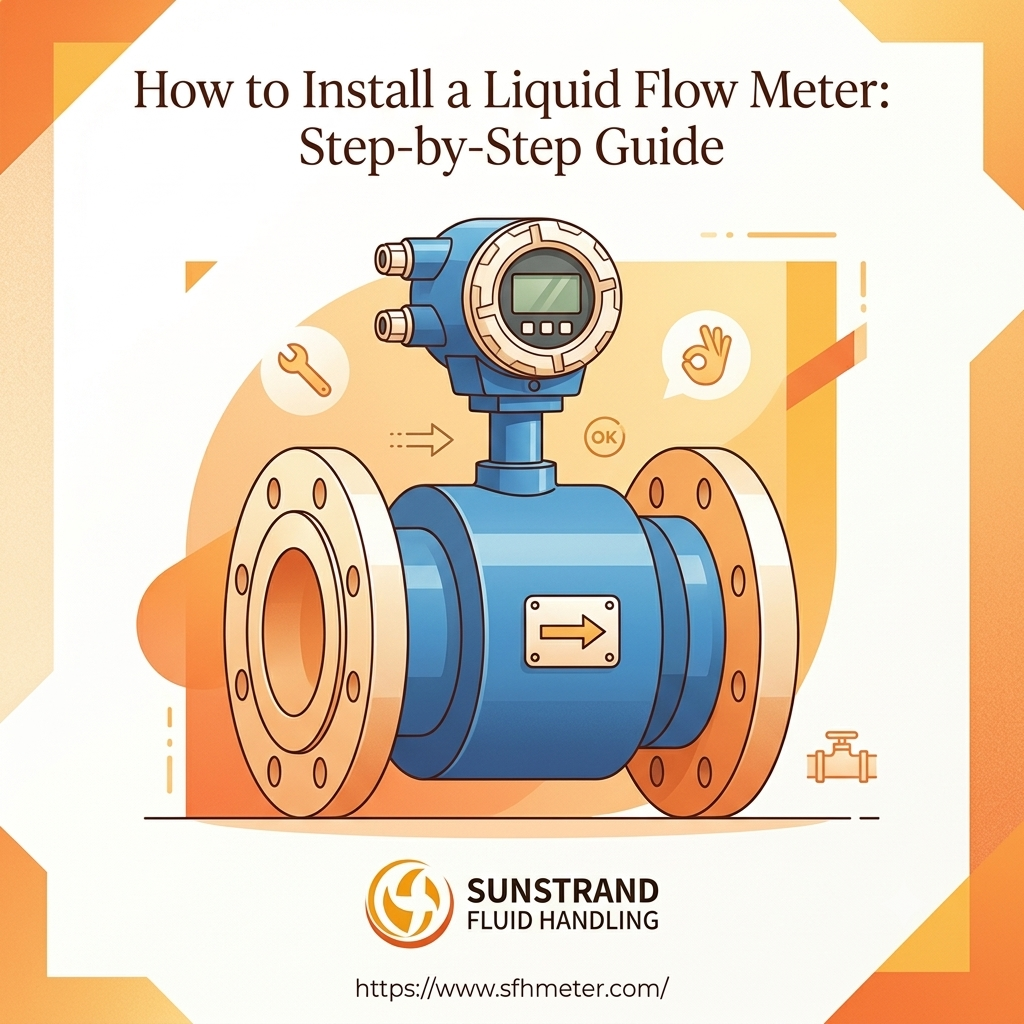
Knowing how to install a liquid flow meter correctly is the single most important factor in achieving reliable, long-term measurement accuracy. Industry data consistently shows that the majority of flow meter performance issues are not caused by defective hardware — they stem directly from improper liquid flow meter installation. Whether you are commissioning a new electromagnetic meter, an ultrasonic unit, or a paddle-wheel sensor, following a structured flow meter installation guide eliminates guesswork and protects your investment.
This guide by Sunstrand — a trusted manufacturer of precision electromagnetic and ultrasonic flow meters — walks industrial engineers, facilities managers, and procurement teams through every stage of the flow meter installation process: pre-installation checks, site selection, flow meter straight pipe requirements, mounting, wiring, grounding, and post-installation calibration. Bookmark this page as your go-to flow meter installation best practices reference.
Pre-Installation Requirements & Site Selection
Before you pick up a wrench, a solid liquid flow meter setup starts with thorough planning. Rushing this stage causes the majority of installation failures encountered in the field.
Fluid Compatibility Check
Verify that the flow meter’s wetted materials — lining, electrodes, seals — are chemically compatible with the process fluid. For aggressive chemicals or high-temperature media, always consult Sunstrand’s chemical compatibility data before specifying a meter. Incorrect material selection leads to corrosion, lining separation, and premature failure.
Additionally, confirm the fluid is single-phase. Electromagnetic meters require a conductive liquid; they cannot measure gases or steam. Thermal mass meters are the right choice for gas applications. Matching the meter type to the fluid is a foundational flow meter installation requirement.
Site Environment
- Temperature & Vibration: Select a location away from heat sources, direct sunlight, and heavy vibration. Reinforce the pipeline on both sides of the meter to absorb any mechanical stress.
- Electromagnetic Interference: Keep magnetic flow meters at least 1 m away from motors, transformers, pumps, and other inductive sources. This is one of the most frequently violated flow meter installation best practices.
- Accessibility: Ensure the installation point allows easy access for future maintenance, calibration, and display reading.
- IP Rating: Respect the meter’s ingress-protection rating. An IP65-rated unit must never be submerged; an IP68 unit should not exceed 5 m of water depth.
Pipeline Condition
The pipe section chosen for flow meter pipe installation must remain completely full of liquid at all times — including periods of zero flow. Partially filled pipes introduce air pockets that corrupt measurements. Avoid high points in the piping system for this reason.
⚠️ Critical Pre-Installation Check
Always drain and isolate the pipe section before installing any inline flow meter. Attempting installation on a live, pressurised line is a serious safety hazard and will damage the meter.
Flow Meter Straight Pipe Requirements
Of all the flow meter installation requirements, the straight pipe rule is the one most often under-estimated on congested industrial sites. Insufficient straight-run lengths produce asymmetric, turbulent velocity profiles that cause the meter to read high or low — sometimes by more than 5%.
Standard Minimum Straight-Run Distances
The general rule of thumb for flow meter straight pipe requirements when no specific manufacturer data is available:
| Upstream Obstruction | Upstream Straight Pipe (× DN) | Downstream Straight Pipe (× DN) |
| Single 90° elbow | 10× DN | 5× DN |
| Two elbows in different planes | 20× DN | 5× DN |
| T-junction / branch tee | 10× DN | 5× DN |
| Partially open valve (upstream) | 20× DN | 5× DN |
| Diameter change / reducer | 5× DN | 3× DN |
DN = nominal pipe diameter. Always defer to Sunstrand’s product-specific datasheet, which takes precedence over these generic figures.
When Straight Pipe Length Is Not Available
On retrofit projects where sufficient straight pipe cannot be accommodated, install a flow conditioner upstream of the meter. Flow conditioners — tubes or vanes positioned parallel to the flow — break up swirl and redistribute the velocity profile, effectively shortening the required upstream run by up to 50%. This is a widely accepted alternative in flow meter installation best practices when plant space is constrained.
Reducer Angle Constraint
If your flow meter pipe installation requires a reducer, keep the taper angle below 7.5°. To find the minimum reducer length:
L = (D – d) × 7.63
L = minimum reducer length (mm) | D = larger pipe diameter (mm) | d = smaller pipe diameter (mm)
Example: Installing a DN 50 sensor downstream of a 90 mm pipe → minimum reducer length = (90 – 50) × 7.63 = 305 mm.
Flow Meter Mounting Position & Orientation
Correct flow meter mounting position directly influences measurement accuracy and the long-term health of the instrument. There is no universal answer — the right choice depends on the meter type and the process conditions.
Horizontal Installation
For horizontal pipelines, mount the flow meter at a low point in the pipe run, not at a high point. High points accumulate air bubbles that interfere with electrode contact in electromagnetic meters or disrupt the signal path in ultrasonic units. For electromagnetic meters installed horizontally, keep the measuring electrodes in the 3 o’clock / 9 o’clock position (horizontal axis) to prevent sediment settling on the lower electrode and air trapping at the upper one.
Vertical Installation
Vertical flow meter pipe installation is often preferred because it naturally ensures a full pipe and a symmetrical velocity profile. The flow direction must be upward — never downward. Upward flow fills the meter body completely, prevents stratification, and provides more stable, accurate readings than downward flow.
✅
Correct — Vertical, Flow Up
Pipe fills completely. Stable laminar flow. No air trapping. Most accurate reading.
❌
Incorrect — Vertical, Flow Down
Gravity drains the pipe. Unstable flow profile. Risk of partial-fill and large measurement error.
❌
Incorrect — Horizontal High-Point
Air bubbles collect at the top of the pipe. Electrode exposed. False zero or erratic readings.
Mechanical Installation Steps
Follow these liquid flow meter installation steps in sequence. Skipping steps — even seemingly minor ones — is a common cause of early failure and warranty voidance.
1
Isolate & Drain the Line
Shut off all upstream and downstream isolation valves. Depressurise the section and fully drain the pipe. Confirm zero pressure before cutting into the line. Safety is the foundation of every flow meter installation guide.
2
Inspect the Meter
Unbox and inspect the flow meter for any transit damage — cracked lining, bent flanges, damaged connectors. Check the datasheet for face-to-face dimensions and confirm it matches the prepared pipe spool piece.
3
Prepare the Pipe Section
Cut the pipe to the correct face-to-face length. Deburr and clean the pipe ends. For threaded connections, ensure thread standards match (NPT vs BSP). Apply PTFE tape to threaded connections for a reliable seal. Do not apply PVC lubricants near polycarbonate or PSU meter bodies.
4
Orient the Flow Arrow
Align the meter so the flow direction arrow on the meter body points in the same direction as the actual process flow. Installing a meter backwards is one of the most common mistakes in liquid flow meter installation and can be impossible to detect without a flow reading.
5
Fit Gaskets & Mount the Meter
Flanged: Place gaskets between the meter flanges and pipe flanges. Insert bolts and tighten in a criss-cross pattern to achieve even compression and prevent lining distortion. Never over-torque. Threaded: Hand-tighten first, then apply the final torque per the datasheet. Avoid tool-tightening union nuts on plastic bodies. Clamp-on: Ensure sensors are in direct contact with the pipe surface; apply the recommended coupling gel for reliable acoustic transmission.
6
Lubricate O-Rings
Lubricate all O-rings with a non-petroleum-based lubricant before assembly. Petroleum-based greases swell elastomeric seals and cause premature leaks — a small detail with a big impact on long-term sealing performance.
Flow Meter Wiring Installation & Grounding
Electrical work is where many technicians feel least confident during flow meter wiring installation. Follow the manufacturer’s wiring diagram precisely. Incorrect wiring causes signal loss, noise injection, and in some cases permanent damage to the transmitter.
Signal & Power Cable Routing
- Route power and signal cables in separate conduits to prevent electrical interference.
- Keep signal cable runs as short as possible — most manufacturers specify a maximum of 30–50 m for standard-shielded cable.
- For electromagnetic meters, the signal cable must be sheathed in a galvanised steel conduit. This reduces lightning and EMI coupling that would otherwise introduce noise into the low-level electrode signal.
- Seal all cable entries with appropriate cable glands to maintain the meter’s IP rating.
Output Types
Modern liquid flow meters typically offer multiple output options. Choose the right output for your system during liquid flow meter setup:
| Output Type | Typical Application | Notes |
| 4–20 mA Analog | PLC / SCADA integration | Industry standard; noise-immune over long runs |
| Pulse / Frequency | Totalising / batch control | Easy to interface with counters and PLCs |
| RS-485 / Modbus | Digital networks, IIoT | Up to 32 devices on one bus; robust in industrial environments |
| Hart Protocol | Advanced diagnostics | Superimposed on 4–20 mA; dual-channel capability |
Grounding — The Most Critical Wiring Step
Improper grounding is responsible for a disproportionate number of noise-related measurement errors. For electromagnetic meters specifically:
- Connect the meter body and both sensor ends to the plant’s equipotential ground bus.
- For non-conductive pipes (PVC, FRP), install grounding rings on both sides of the meter to provide a reference for the measuring electrodes.
- Install lightning arresters on both power and signal cables where outdoor installation is required. The arrester ground wire must be no longer than 1 m and use a multi-strand copper core cable with a cross-sectional area of at least 6 mm².
Need Wiring Support?
Not sure which output configuration matches your system?
Sunstrand’s engineers provide free pre-sales technical support for panel wiring, PLC integration, and site-specific installation advice.
Talk to an Engineer →
Post-Installation Calibration & Verification
Completing the physical and electrical flow meter installation steps is not the finish line. Post-installation verification confirms that the meter is performing to specification before it goes into service.
Leak Check
Slowly re-pressurise the line and inspect all flange faces, threaded joints, and cable glands for leaks. Check visually and with a pressure gauge. Do not bring the system to full operating pressure until all joints have been confirmed leak-free.
Zero Calibration
For electromagnetic meters, perform a zero-flow calibration with the pipe completely full of stationary liquid. Close both isolation valves, confirm zero velocity, and run the zero-point adjustment procedure via the local display or HART communicator. This eliminates any offset errors introduced by the installation environment.
Live Flow Verification
Open the isolation valves and bring the process to its normal operating flow rate. Compare the meter reading against a reference — a calibrated test meter, a weigh tank, or a master meter. A well-installed meter should read within its specified accuracy band (typically ±0.2–0.5% for electromagnetic meters).
Documentation
Record the installation date, location tag, serial number, zero-calibration result, and initial flow reading in your maintenance management system. This baseline data is essential for diagnosing drift and planning future calibration intervals — a key part of lifecycle flow meter installation best practices.
💡 Pro Tip: Calibration Frequency
Most industrial electromagnetic flow meters are factory-calibrated to traceable standards. For critical billing or custody-transfer applications, arrange independent on-site verification or periodic return to a NIST-traceable calibration laboratory.
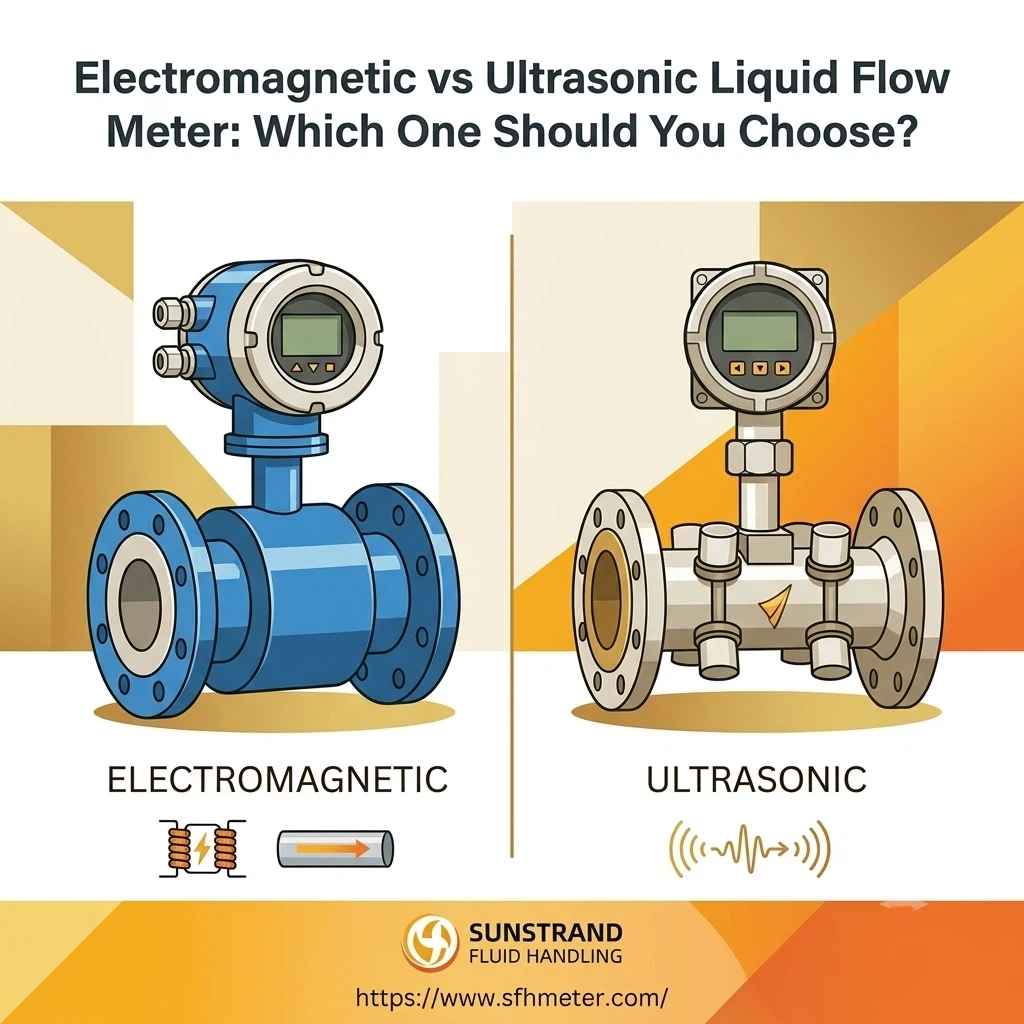
Type-Specific Installation Notes
Electromagnetic (Mag) Flow Meters
- Fluid must be electrically conductive (minimum ~5 µS/cm for most models).
- Not suitable for gases, steam, or non-conductive hydrocarbons.
- Install grounding rings on plastic pipes to establish electrode reference potential.
- Avoid installation near large magnetic field sources.
Ultrasonic (Clamp-On) Flow Meters
- No pipe cutting required — sensors mount externally, making them ideal for retrofitting on existing lines.
- Pipe material, wall thickness, and liner material significantly affect signal quality. Input accurate pipe data during liquid flow meter setup.
- Apply the manufacturer-specified coupling gel between sensor and pipe surface. Insufficient coupling is the leading cause of ultrasonic meter read-failure.
- Avoid heavily corroded pipe sections — internal scale changes the effective internal diameter and distorts readings.
Paddle Wheel Flow Meters
- Must be installed in fully laminar, non-turbulent flow — they are the most sensitive to upstream disturbances.
- Some models are horizontal-only; always verify orientation requirements in the datasheet.
- Clean the rotor and housing regularly in applications with suspended solids or biological growth.
Rotameters (Variable Area Meters)
- Must be installed vertically with upward flow. Any deviation from vertical introduces a gravity-related measurement error.
- The fluid’s specific gravity must match the meter’s calibrated fluid; consult a correction factor chart for other fluids.
Quick Installation Checklist
Use this at-a-glance checklist before signing off on any liquid flow meter installation:
☐ Fluid compatibility confirmed (material, conductivity, temperature, pressure)
☐ Pipe always full; no high-point installation
☐ Straight pipe requirements met (upstream & downstream)
☐ Flow arrow aligned with process flow direction
☐ Correct orientation (vertical upflow or horizontal low-point)
☐ Gaskets and O-rings in place; non-petroleum lubricant used
☐ Flange bolts torqued in criss-cross pattern
☐ Wiring matches manufacturer diagram; power and signal cables segregated
☐ Grounding completed; grounding rings on plastic pipe where required
☐ IP rating respected; cable glands sealed
☐ Leak test passed at operating pressure
☐ Zero calibration performed; live reading verified against reference; documentation complete
Frequently Asked Questions
1: What is the minimum straight pipe length required before and after a flow meter?
As a general rule of thumb, allow at least 10× the pipe diameter (DN) upstream and 5× DN downstream for a single 90° elbow. Two elbows in different planes require 20× DN upstream. Always consult the Sunstrand product datasheet for model-specific straight pipe requirements, as these take precedence. If sufficient straight pipe cannot be achieved on-site, install a flow conditioner upstream of the meter to stabilise the velocity profile.
2: Can a liquid flow meter be installed vertically with downward flow?
No. Vertical installation must always have upward flow. Downward flow allows gravity to partially drain the meter body, creating a partial-fill condition and producing significant measurement errors. Upward flow keeps the meter body completely full and produces a stable, symmetric velocity profile.
3: How do I ground an electromagnetic flow meter on a plastic (non-conductive) pipe?
Install grounding rings — also called earthing rings — on both sides of the meter. These stainless-steel or Hastelloy rings make direct contact with the process fluid and are connected to the plant’s ground bus. Without them, the measuring electrodes lack a stable reference potential, leading to noisy, erratic signals. Some Sunstrand electromagnetic meters include integrated grounding rings; verify in the product datasheet.
4: What is the difference between inline and clamp-on flow meter installation?
Inline meters (flanged or wafer) are cut directly into the pipeline, providing the highest accuracy and lowest susceptibility to pipe-wall effects. They require shutting down the line for installation. Clamp-on / non-invasive meters attach to the outside of the pipe with no pipe cutting, making them ideal for retrofitting and for lines that cannot be taken out of service. They are slightly less accurate and more sensitive to pipe-wall condition, scale, and material.
5: Why does my newly installed flow meter read zero even when fluid is flowing?
The most common causes are: (1) the meter is installed backwards — check the flow arrow on the body; (2) the pipe is not fully full — air pockets break the electrode circuit; (3) for electromagnetic meters, the fluid conductivity is below the meter’s minimum threshold; (4) wiring is incorrect — re-check the wiring diagram; (5) zero calibration was not performed with a full, stationary pipe. Work through each item systematically before concluding the meter is defective.
6: How often should a liquid flow meter be recalibrated after installation?
For most industrial process monitoring applications, a 12–24 month calibration interval is standard. For billing, custody transfer, or regulatory compliance, annual calibration against a traceable standard is typically required. Electromagnetic meters with no moving parts exhibit very low drift; rotameters and paddle-wheel meters with wetted rotating parts may need more frequent inspection in abrasive or scaling applications.
7: Can I install a flow meter on a pressurised pipe without shutting down the system?
For clamp-on ultrasonic meters, yes — sensors are mounted externally, so no pipe penetration is required and the line remains live throughout installation. For inline meters, hot-tapping is technically possible on some pipe materials and pressure classes, but it is a specialist task requiring certified hot-tap equipment and experienced personnel. In most cases, scheduling a planned shutdown is safer and more cost-effective.
8: What causes erratic or unstable flow meter readings after installation?
Common causes include: (1) air bubbles or gas pockets in the liquid — review the pipeline layout and eliminate high points; (2) insufficient upstream straight pipe — turbulence from nearby elbows or valves creates a swirling flow that the meter cannot average correctly; (3) poor or missing grounding — especially on electromagnetic meters, which pick up stray electrical currents as false flow signals; (4) pipeline vibration — reinforce the pipe on both sides of the meter; (5) fluid conductivity fluctuations in electromagnetic applications.
9: Does the flow meter need to be the same nominal size as the pipeline?
Not necessarily, but size reduction must be done carefully. Reducing the meter bore below the pipeline diameter increases velocity, which can improve measurement resolution at low flow rates. However, the reducer must have a taper angle below 7.5° (use the formula L = (D – d) × 7.63 to determine the minimum reducer length). Abrupt reducers create turbulence that undermines accuracy. Always confirm the selected meter size covers the expected flow rate range (minimum to maximum) within the meter’s calibrated turndown ratio.
10: How do I protect an outdoor flow meter installation from lightning and moisture?
Four measures work together: (1) Grounding — both ends of the sensor earthed to a low-impedance ground bus is the primary defence; (2) Conduit shielding — run signal cables in a grounded galvanised steel conduit, maximum 50 m length; (3) Equipotential bonding — sensor, transmitter, and all metallic pipe components at the same ground potential; (4) Lightning arresters — installed on both power and signal cables, with ground wires no longer than 1 m using ≥ 6 mm² multi-strand copper. For UV protection, install a shading cover over any polycarbonate or transparent meter body.
Sunstrand Flow Meters
Ready to Install? Start with the Right Meter.
Sunstrand supplies electromagnetic and ultrasonic flow meters pre-configured for your pipe size, fluid type, and output requirements — shortening commissioning time and eliminating compatibility guesswork.
Related Resources
Keep Learning: Flow Meter Guides from Sunstrand
Electromagnetic Flow Meter Product Range
Explore Sunstrand’s full DN15–DN2000 electromagnetic meter lineup with flanged and wafer options.
View Products →