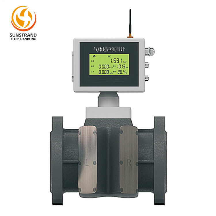
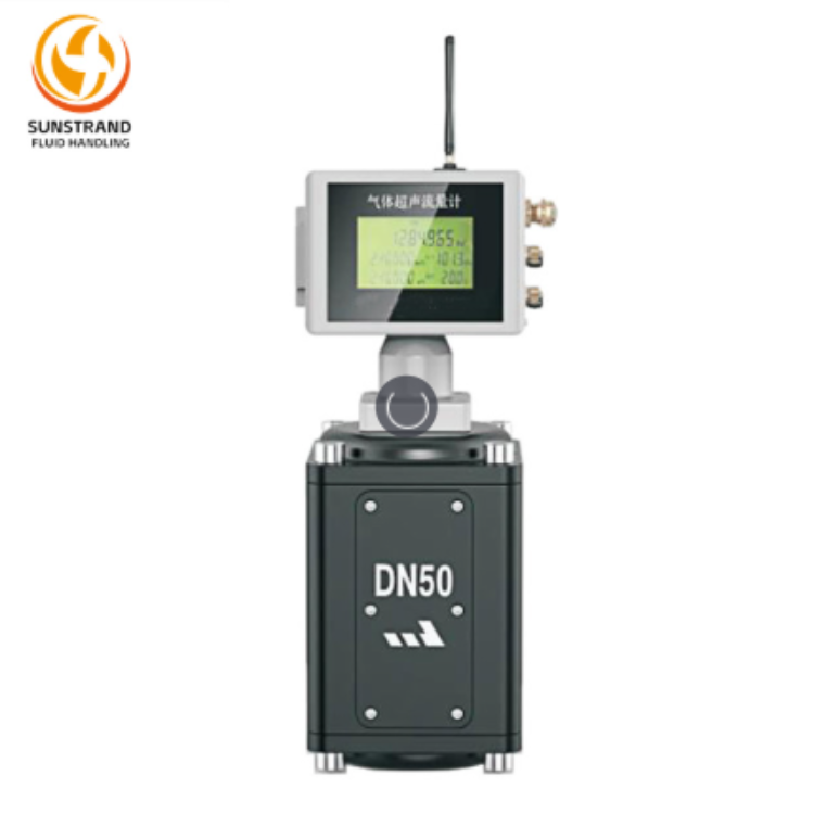
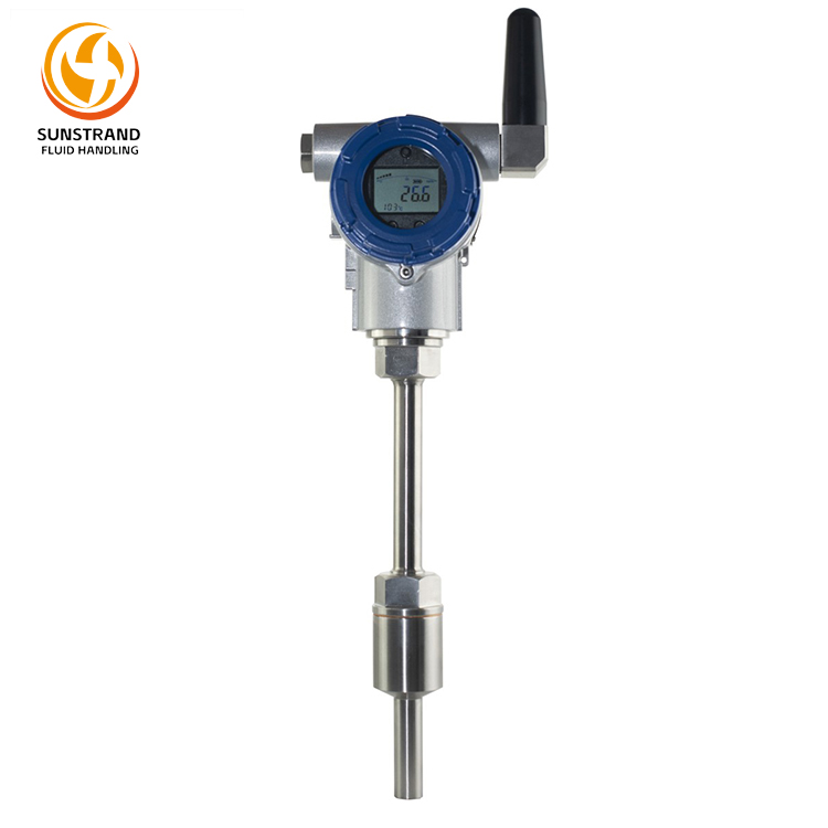
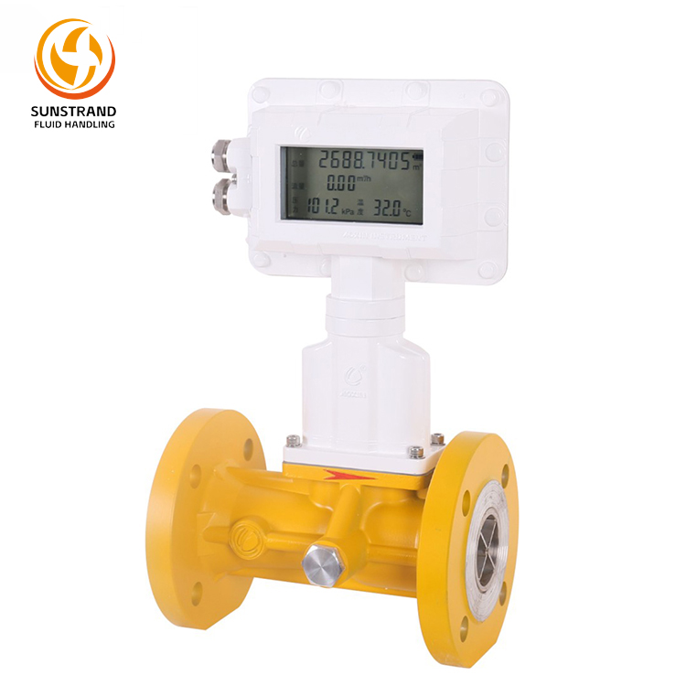
The ALS-U Gas Ultrasonic Flow Meter is a dual-channel, low-power consumption product developed in accordance with GB/T 18604. It requires no external power supply and references the following standards: GB/T 32201 Gas meters (OIMLR137-1&2:2012), GB/T 34041.1 Measurement of fluid flow in closed conduitsUltrasonic meters for gasPart 1: Meters for custody transfer and allocation measurement, and GB/T 28848 Smart Gas Flow Meter. It is primarily designed for accurate measurement of natural gas flow rates.
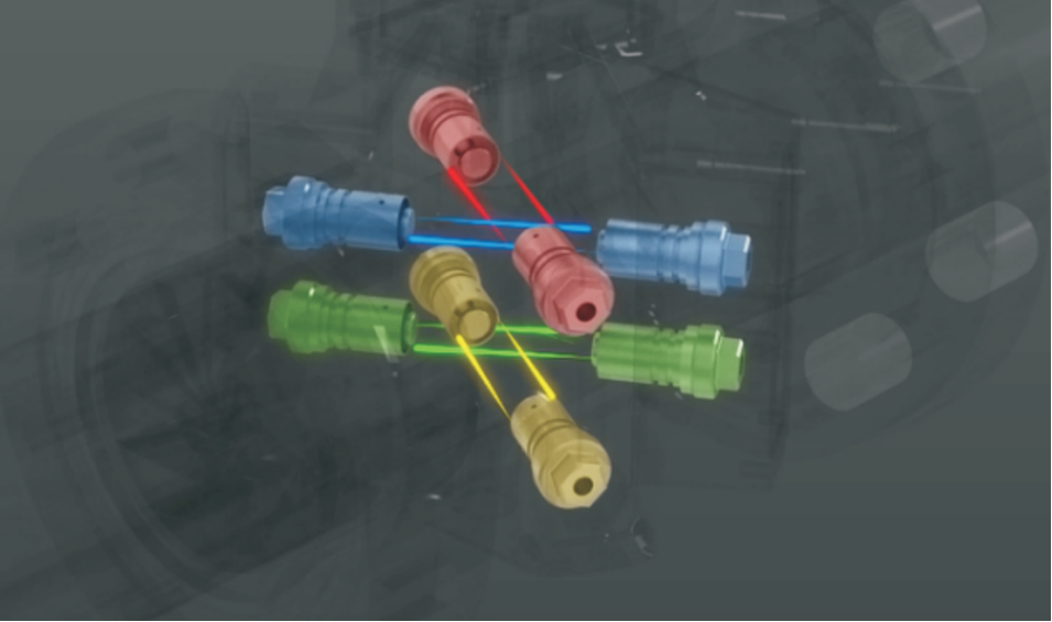
Equipped with two ultrasonic measurement channels, it enables high-precision measurement of gaseous media (especially natural gas and city gas) in pipelines. The flowmeter processes ultrasonic signals from paired transducers through a signal acquisition circuit and a microcontroller-based processing unit. It displays, stores, and records measurement results. Featuring an RS485 serial communication interface (supporting MODBUS protocol), it allows parameter configuration via host computer software. Additionally, its pulse output signal function supports flowmeter verification and integration with IC card controllers.
The ALS-U Gas Ultrasonic Flow Meter is ideal for accurate and reliable trade settlement measurement of medium/low-pressure, low-flow-rate, high-quality natural gas in downstream city gas networks. It is particularly suited for gas metering in industrial, small-scale industrial, commercial, and food service sectors. As cities transition to smart gas management systems, this flowmeter stands out as the optimal choice.
Measurement Principle:
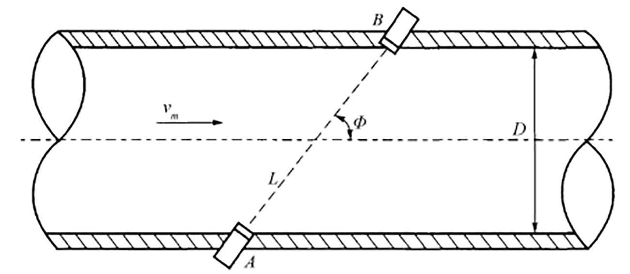
The gas ultrasonic flowmeter operates based on the Time Difference Method, which correlates the transit time of ultrasonic waves through a flowing medium with the flow rate. The actual transit speed of ultrasonic waves in the fluid is determined by both the static speed of sound (C) of the medium and the component of the fluid’s axial average velocity (Vm) in the wave propagation direction.
As shown in Figure 1, the relationship between upstream/downstream transit times and the relevant parameters is:

Where:
tup: Upstream transit time of ultrasonic waves in the fluid;
tdown: Downstream transit time of ultrasonic waves in the fluid;
Cf: Sound velocity in the fluid;
Vm: Axial average velocity of the fluid;
Φ: Acoustic path angle.
|
|
|
Figure 1 Schematic Diagram
|
From Equation (1), the fluid velocity expression is derived as:
By combining the measured velocities Vt(i=1,2,•••k) from multiple acoustic paths through mathematical functions, the average pipe flow velocity is estimated . Multiplying this by the cross-sectional area A yields the volumetric flow rate qv, as shown in Equations (3) and (4):

Where:
k: Number of acoustic paths.
Gas Ultrasonic Flow Meter Selection
Model Coding:

|
Gas Ultrasonic Flow Meter Model Selection Code Cross-Reference Table
|
|
1
|
Product Type
|
A-Pipeline Type
|
|
B-Insertion Type
|
|
2
|
Nominal Diameter
|
020-DN20
|
125-DN125
|
|
025-DN25
|
150-DN150
|
|
032-DN32
|
200-DN200
|
|
050-DN50
|
250-DN250
|
|
080-DN80
|
300-DN300
|
|
100-DN100
|
|
|
3
|
Nominal Pressure
|
16-PN16
|
100-PN100
|
|
25-PN25
|
250-PN250
|
|
40-PN40
|
420-PN420
|
|
64-PN64
|
|
|
4
|
Connection Method
|
1-Flange Type
|
|
2-Clamp Type
|
|
5
|
Measuring Tube Material
|
1-Carbon Steel
|
|
2-316 Stainless Steel
|
|
3-304 Stainless Steel
|
|
6
|
Measuring Tube Wall Thickness
|
Direct Input
|
|
7
|
Number of Measurement Paths
|
1-Two-Path
|
|
2-Three-Path
|
|
3-Four-Path
|
|
4-Five-Path
|
|
8
|
Transducer (Probe)
|
1-Standard Type
|
|
2-Smart Type
|
|
9
|
Transducers Installation Method
|
1-Bracket Installation
|
|
2-Direct Installation
|
|
10
|
Ex-protected design & Ingress Protection
|
1-Ex d mb IIC T5/T6 Gb IP 66
|
|
2-Ex d mb IIC T5/T6 Gb IP 67
|
|
11
|
Structural Form
|
1-Integrated Type
|
|
2-Separated Type
|
|
12
|
Power Supply
|
1-Built-in 3.6V Li-battery (no output)
|
|
2-DC24V
|
|
3-AC220V
|
|
13
|
Output Signal
|
1-Pulse
|
|
2-Pulse, 4-20mA+HART
|
|
3-Pulse, 4-20mA+Modbus-RS485
|
|
4-Pulse, GPRS
|
When placing orders, customers should consult the manufacturer regarding specific models and specifications based on their actual application conditions to avoid potential complications or losses.
Overview:
ALS-U Series Gas Ultrasonic Flow Meter are manufactured using advanced German technology, with key components being original imported. They feature high reliability, stable performance, long service life, etc. This new type of precision metering instrument offers high accuracy and high reliability. It can be widely applied for gas flow measurement in industries such as urban gas, petroleum, chemical engineering, power, and metallurgy.
Features:
1.Accurately measures unidirectional gas flow under medium and low pressure conditions, featuring a wide measurement range and a turndown ratio exceeding 65:1.
2.Multi-layer shielding for electric and magnetic fields, providing high noise immunity.
3.Automatic zero-drift correction, ensuring accuracy unaffected by environmental conditions.
4.Measurement accuracy: ±1.0% /±1.5%
5.Complies with international standard ISO 17089, American AGA Report No.9, and Chinese standard GB/T 18604-2014.
Specification:
|
Nominal Diameter
|
DN80~DN250
|
|
Nominal Pressure
|
0~1.6MPa
|
|
Flow Velocity Range
|
0.03m/s~120m/s
|
|
Ingress Protection
|
IP67
|
|
Converter Shell Material
|
Aluminum Alloy
|
|
Ultrasonic transducer Material
|
316L Stainless Steel,, 304 Stainless Steel
|
|
Suitable Media
|
Gas
|
|
Accuracy
|
±1.0%, ±1.5%
|
|
Medium Temperature
|
-20℃~60℃
|
|
Ex-protected design
|
Ex d mb ⅡC T5/T6 Gb
|
|
Output Signal
|
Pulse/Frequency 5kHz, 4~20mA, 4~20mA+HART, RS485 (Modbus RTU)
|
|
Electrical Interface
|
M20×1.5 Internal Thread (M18×1.5 Internal Thread, 1/2NPT Internal Thread, are customizable)
|
|
Ingress Protection
|
Built-in 3.6V Li-battery (3+ years life, local display only, no output), AC220V±10% 50Hz, DC24V±5%
|
|
Ambient Temperature
|
-40℃~80℃ (requires protective measures below this threshold)
|
|
Ambient Humidity
|
5%~95%
|
|
Response Time
|
0.03s~1s
|
Note: The instrument flanges comply with GB/T 9119-2010. For special requirements, the applicable standard must be specified (ASME B16.5-2009 Pipe Flanges and Flanged Fittings or the Ministry of Chemical Industry standard HG/T 20615-2009 Steel Pipe Flanges (Class Series))
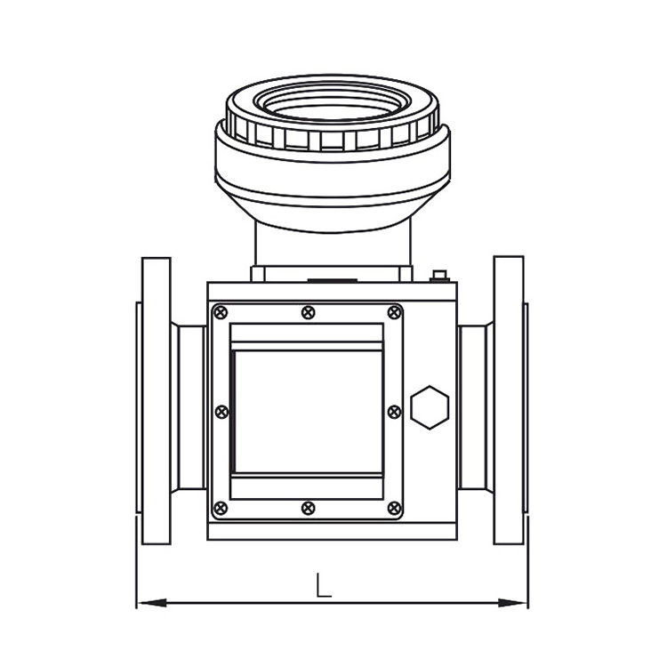
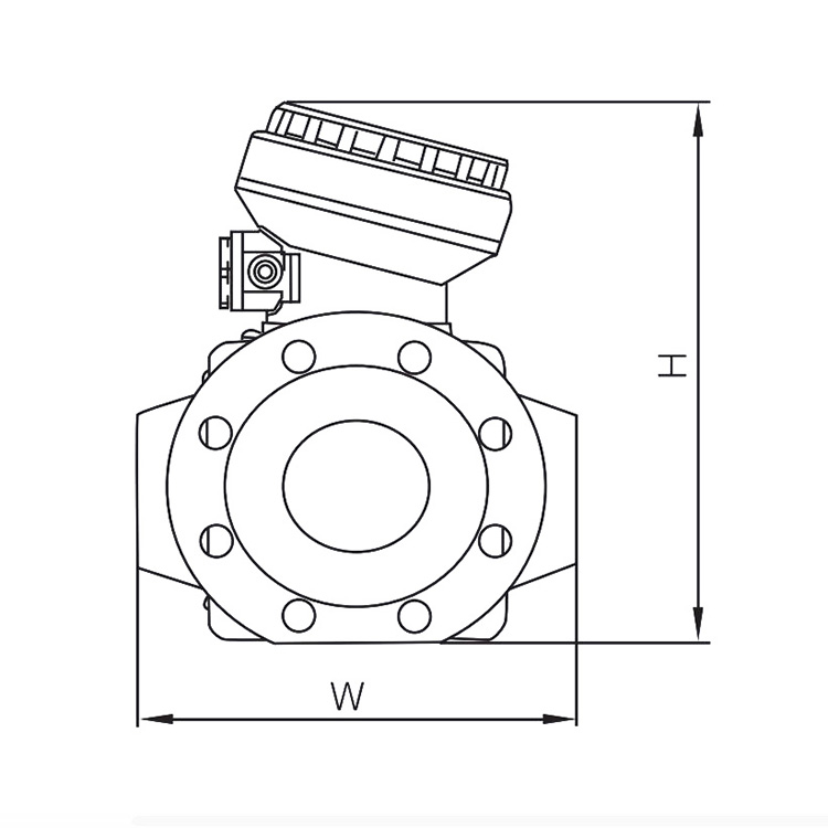
Installation Size:
The flowmeter body should be installed horizontally as much as possible; vertical installation is not recommended. Additionally, inverted installation (with the LCD display window facing downward) or horizontal installation is strictly prohibited. This prevents liquid accumulation in the cavities of the transducer mounting holes and temperature/pressure sensor ports, which could affect ultrasonic transmission (unless the gas is dry) and compromise measurement accuracy.
In applications where the gas medium is contaminated, an effective gas filter may be installed upstream of the flowmeter—at a position that does not interfere with the measured gas flow field.
|
Nominal Diameter
|
Nominal Pressure
|
Flange Inner Diameter(mm)
|
Overall Dimensions(mm)
|
Weight(kg)
|
|
DN25
|
PN16
|
26
|
L
|
W
|
H
|
7.5
|
|
DN32
|
PN16
|
30
|
180
|
160
|
275
|
7.5
|
|
DN40
|
PN16
|
40
|
180
|
160
|
280
|
8
|
|
DN50
|
PN16
|
50
|
180
|
160
|
280
|
8
|
|
DN80
|
PN16
|
78
|
240
|
220
|
310
|
13
|
|
DN100
|
PN16
|
100
|
300
|
230
|
330
|
15
|
|
DN150
|
PN16
|
150
|
300
|
300
|
410
|
65
|
|
DN200
|
PN16
|
200
|
400
|
400
|
460
|
100
|
Note:
1. The body lengths listed in the table above refer to standard flowmeter products. Custom body length requirements must follow the technical agreement with the customer.
2.For larger nominal diameters or higher nominal pressure specifications, relevant documentation may be requested from our company.