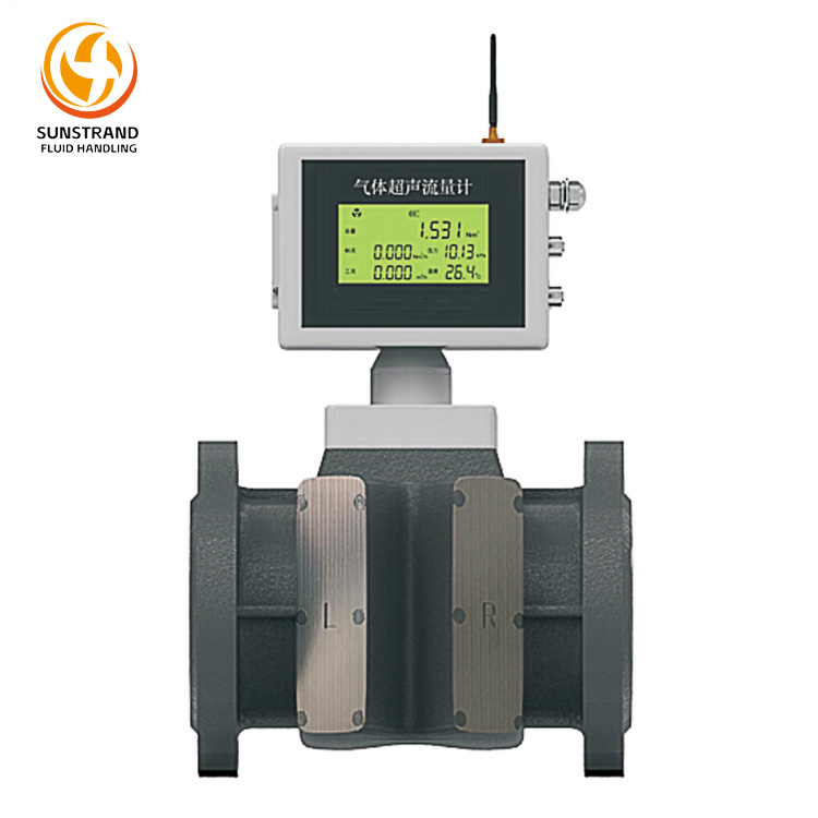
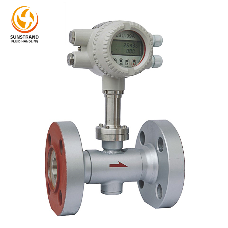
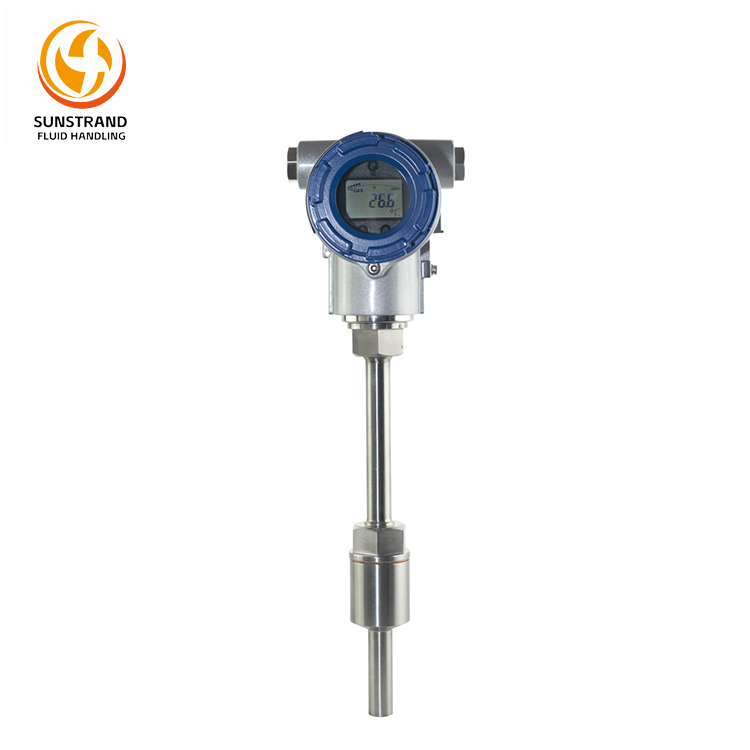
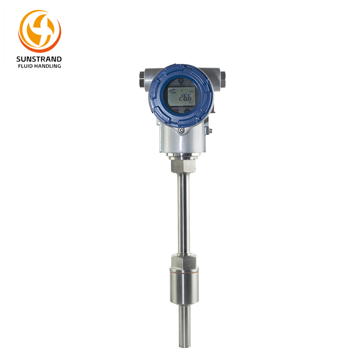
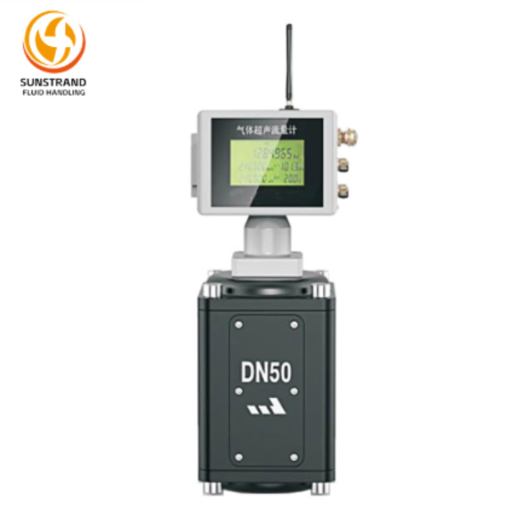
The ALS-U Gas Ultrasonic Flow Meter is a dual-channel, low-power consumption product developed in accordance with GB/T 18604. It requires no external power supply and references the following standards: GB/T 32201 Gas meters (OIMLR137-1&2:2012), GB/T 34041.1 Measurement of fluid flow in closed conduitsUltrasonic meters for gasPart 1: Meters for custody transfer and allocation measurement, and GB/T 28848 Smart Gas Flow Meter. It is primarily designed for accurate measurement of natural gas flow rates.
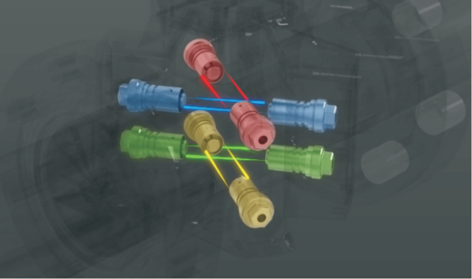
Equipped with two ultrasonic measurement channels, it enables high-precision measurement of gaseous media (especially natural gas and city gas) in pipelines. The flowmeter processes ultrasonic signals from paired transducers through a signal acquisition circuit and a microcontroller-based processing unit. It displays, stores, and records measurement results. Featuring an RS485 serial communication interface (supporting MODBUS protocol), it allows parameter configuration via host computer software. Additionally, its pulse output signal function supports flowmeter verification and integration with IC card controllers.
The ALS-U Gas Ultrasonic Flow Meter is ideal for accurate and reliable trade settlement measurement of medium/low-pressure, low-flow-rate, high-quality natural gas in downstream city gas networks. It is particularly suited for gas metering in industrial, small-scale industrial, commercial, and food service sectors. As cities transition to smart gas management systems, this flowmeter stands out as the optimal choice.
Measurement Principle:
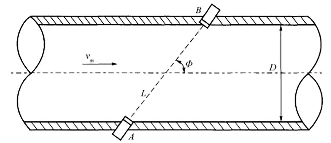
The gas ultrasonic flowmeter operates based on the Time Difference Method, which correlates the transit time of ultrasonic waves through a flowing medium with the flow rate. The actual transit speed of ultrasonic waves in the fluid is determined by both the static speed of sound (C) of the medium and the component of the fluid’s axial average velocity (Vm) in the wave propagation direction.
As shown in Figure 1, the relationship between upstream/downstream transit times and the relevant parameters is:

Where:
tup: Upstream transit time of ultrasonic waves in the fluid;
tdown: Downstream transit time of ultrasonic waves in the fluid;
Cf: Sound velocity in the fluid;
Vm: Axial average velocity of the fluid;
Φ: Acoustic path angle.
|
|
|
Figure 1 Schematic Diagram
|
From Equation (1), the fluid velocity expression is derived as:
By combining the measured velocities Vt(i=1,2,•••k) from multiple acoustic paths through mathematical functions, the average pipe flow velocity is estimated . Multiplying this by the cross-sectional area A yields the volumetric flow rate qv, as shown in Equations (3) and (4):

Where:
k: Number of acoustic paths.
Gas Ultrasonic Flow Meter Selection
Model Coding:

|
Gas Ultrasonic Flow Meter Model Selection Code Cross-Reference Table
|
|
1
|
Product Type
|
A-Pipeline Type
|
|
B-Insertion Type
|
|
2
|
Nominal Diameter
|
020-DN20
|
125-DN125
|
|
025-DN25
|
150-DN150
|
|
032-DN32
|
200-DN200
|
|
050-DN50
|
250-DN250
|
|
080-DN80
|
300-DN300
|
|
100-DN100
|
|
|
3
|
Nominal Pressure
|
16-PN16
|
100-PN100
|
|
25-PN25
|
250-PN250
|
|
40-PN40
|
420-PN420
|
|
64-PN64
|
|
|
4
|
Connection Method
|
1-Flange Type
|
|
2-Clamp Type
|
|
5
|
Measuring Tube Material
|
1-Carbon Steel
|
|
2-316 Stainless Steel
|
|
3-304 Stainless Steel
|
|
6
|
Measuring Tube Wall Thickness
|
Direct Input
|
|
7
|
Number of Measurement Paths
|
1-Two-Path
|
|
2-Three-Path
|
|
3-Four-Path
|
|
4-Five-Path
|
|
8
|
Transducer (Probe)
|
1-Standard Type
|
|
2-Smart Type
|
|
9
|
Transducers Installation Method
|
1-Bracket Installation
|
|
2-Direct Installation
|
|
10
|
Ex-protected design & Ingress Protection
|
1-Ex d mb IIC T5/T6 Gb IP 66
|
|
2-Ex d mb IIC T5/T6 Gb IP 67
|
|
11
|
Structural Form
|
1-Integrated Type
|
|
2-Separated Type
|
|
12
|
Power Supply
|
1-Built-in 3.6V Li-battery (no output)
|
|
2-DC24V
|
|
3-AC220V
|
|
13
|
Output Signal
|
1-Pulse
|
|
2-Pulse, 4-20mA+HART
|
|
3-Pulse, 4-20mA+Modbus-RS485
|
|
4-Pulse, GPRS
|
When placing orders, customers should consult the manufacturer regarding specific models and specifications based on their actual application conditions to avoid potential complications or losses.
Overview:
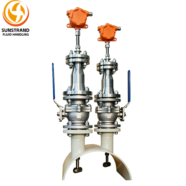
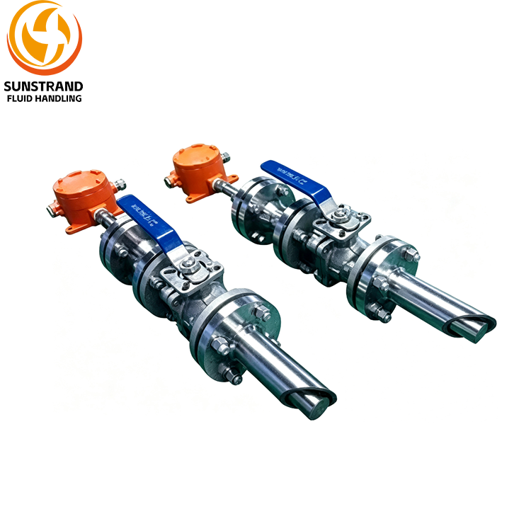
The ALS insertion-type ultrasonic flowmeter is specifically designed for low-pressure, large-diameter gas flow measurement. It offers stable and reliable measurement, with low start-up flow, a wide turndown ratio, data logging capacity of over 100,000 records, and no moving parts.
The product features flexible configuration options, from single-path to quadruple-path, and the transmitter and sensors are installed separately. The transmitter can accept a signal from an external temperature transmitter to perform temperature compensation calculations for the flow in the pipe.
Under normal operating conditions and with proper maintenance, the service life is up to 10 years. It is widely used for flow measurement of various gas media (air, fuel gas, waste gas, flare gas, steam, etc.) in process industry installations.
Applications:
- Measurement of natural gas, ethylene, propylene, hydrogen, air, etc. in the petrochemical industry;
- Flow measurement of various gaseous chemical products;
- Material balance measurement in natural gas transmission pipelines;
- LNG (liquefied natural gas);
- Low- and high-pressure steam.
Specification:
|
Acoustic Paths
|
Single-path, Dual-path, Triple-path, Quadruple-path
|
|
Accuracy Class
|
Single-path: ±2.0%; Dual-path: ±1.0%; Triple-path: ±0.5% ~ ±1.0%; Quadruple-path: ±0.5%
|
|
Turndown Ratio
|
4000:1
|
|
Nominal Diamete
|
DN200 ~ DN2800
|
|
Nominal Pressure
|
0 ~ 21 MPa
|
|
Flow Velocity Range
|
0.03 m/s ~ 120 m/s
|
|
Operating Principle
|
Transit-time difference method
|
|
Measured Media
|
Coal gas, flare gas, dry gas, natural gas, air, etc.
|
|
Power Supply
|
Standard: 85–265 VAC, 50/60 Hz; Optional: 12–28 VDC, ±5%
|
|
Display
|
LCD screen
|
|
Operating Language
|
English | Chinese
|
|
Response Time
|
0.03 ~ 1 s
|
|
Transmitter Enclosure
|
Aluminium alloy
|
|
Ex-protected design
|
Ex d IIC T6
|
|
Ingress Protection
|
Transmitter IP66 / Sensors IP68
|
|
Operating Temperature
|
Transmitter: –40 °C ~ 70 °C (Note: LCD operable down to –25 °C)
|
|
Sensor: –40 °C ~ 450 °C (optional)
|
|
Probe Material
|
Standard: Ti-alloy; consult factory for other materials
|
|
Measurement Functions
|
Volumetric flow rate at operating conditions, volumetric flow rate at standard conditions, mass flow rate
|
|
Inputs / Outputs & Communication
|
|
Signal I/O
|
One 4–20 mA current output, one 0–5 kHz frequency output
|
|
Communication
|
One RS485 (MODBUS-RTU), one serial port output
|
|
Data Logging
|
|
Logged Content
|
Average flow velocity, average sound velocity, temperature, volumetric flow (operating), mass flow, accumulated volume (operating),
accumulated mass, signal strength per channel, signal-to-noise ratio, gain value, transit time, flow velocity, sound velocity
|
|
Logging Interval
|
1 s / 10 s / 30 s / 60 s / 10 min / 30 min / 60 min
|
|
Logging Capacity
|
≥ 100,000 data records
|