Warning: mysqli_query(): (HY000/1032): Can't find record in 'wp_options' in /www/wwwroot/dayin.junj.cc/wp-includes/class-wpdb.php on line 2351 LSU-99A-W Wireless Vortex Flowmeter Gas Flow Meter
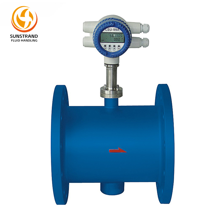
The Wireless Gas Vortex Flow Meter LSU-99A-W is a new-generation flow instrument based on the principle of “Kármán vortex street” wireless transmission. It is widely used in digital oilfield construction projects (such as metering stations, water distribution stations, injection allocation stations, valve groups, water source wells, and injection wells, among other production sites) utilizing Zigbee or WIA-PA technology.
The LSU-99A Series Gas Vortex Flow Meter operates on the Kármán vortex street principle. It combines the characteristics of both vortex flowmeters and electromagnetic flowmeters, which belong to the category of velocity-type flow measurement instruments.
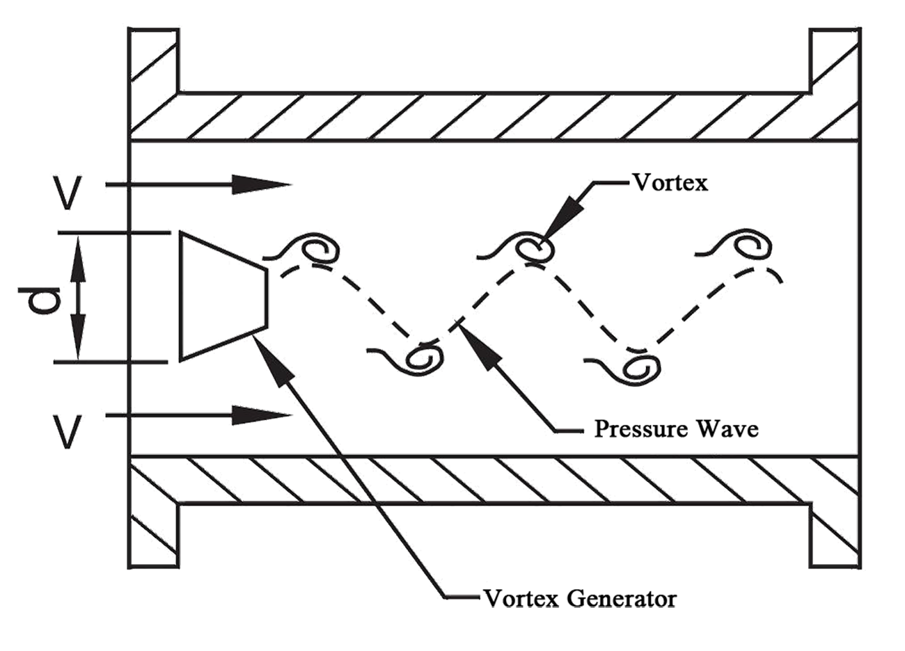
The operating principle is illustrated in Figure 1.
The bluff body is mounted within the measuring pipe. An insulated electrode rod is installed at a specified distance downstream of the generator, with a pair of permanent magnets vertically aligned between the generator and electrode.
When fluid flows past the bluff body at velocity V, alternating vortices are produced on both sides of the generator, forming a “vortex street” (Figure 2). These vortices intersect the magnetic flux lines perpendicularly, generating periodic induced potential pulses. Within defined Reynolds number ranges, the vortex shedding frequency f on a single side exhibits linear proportionality to the fluid velocity V, as defined by the following formula:
f=St·V/d
Where:
V: Fluid velocity on both sides of the generator (m/s).
d: Characteristic width of the bluff body’s flow-facing surface (m).
St: Strouhal number, a constant within specific Reynolds number ranges for a given bluff body geometry.
With fixed pipeline and generator geometry, the flow rate QV becomes directly proportional to frequency f. The weak frequency-dependent signals are amplified, shaped, and processed via microprocessor to generate display readings and standardized outputs (e.g., 4–20 mA).
Figure 1 Vortex Flowmeter Structure Schematic
Figure 2 bluff body Schematic
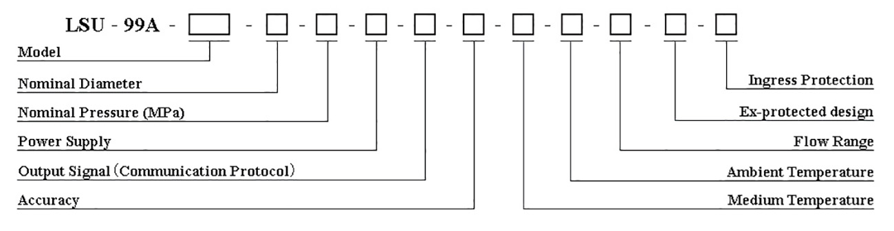
Gas Vortex Flow Meter Selection
Model Coding:
Technical Parameters
Overview:
The Wireless Gas Vortex Flow Meter LSU-99A-W is a new-generation flow instrument based on the principle of “Kármán vortex street” wireless transmission. It is widely used in digital oilfield construction projects (such as metering stations, water distribution stations, injection allocation stations, valve groups, water source wells, and injection wells, among other production sites) utilizing Zigbee or WIA-PA technology.
Features:
1.Employs Zigbee wireless communication technology.
2.Features integrated temperature and pressure compensation.
3.Outputs pulse signals proportional to flow rate with no zero drift.
4.Low pressure loss, suitable for metering sandy sewage and clean water.
5.Equipped with an external power supply interface, compatible with 24V DC external power sources.
6.Low power consumption design: two 3.6V lithium batteries ensure a battery life of over 2 years, and battery replacement is effortless.
7.Electrodes and piezoelectric crystal probes offer low resistance to liquids, reliable performance, and a long service life.
Specification:
Nominal Diameter
DN20~DN50
Nominal Pressure
16MPa, 25MPa, 32MPa
Flow Range
Selectable from 0.3~30m³/h
Ingress Protection
IP65
Suitable Media
Water, Wastewater, Gas
Turndown Ratio
1:10, 1:15, 1:20
Accuracy
±0.5%, ±1.0%, ±1.5%
Medium Temperature
0~100℃
Ex-protected design
Ex d IIC T4 Gb, Ex ia ⅡC T4
Signal Transmitter Module
Frequency Range: 2400~2483.5MHz
Gain: ≥2dBi
Polarization: Linear
Radiation Pattern: Omnidirectional
Connection Type: MMCX (Customizable)
Transmission Distance: ≥200m
(In Unobstructed Line of Sight Conditions)
Output Signal
Zigbee, A11-GRM, RS485(MODBUS)
Power Supply
Built-in 3.6 V Li-battery (2+ years life, local display only, no output), 24 V DC±5%, 12 V DC±20%(Solar Photovoltaic)
Ambient Temperature
-40℃~55℃(requires protective measures below this threshold)
Ambient Humidity
5%~95%
Note: The instrument flanges comply with GB/T 9115-2010. For special requirements, the applicable standard must be specified (ASME B16.5-2009 Pipe Flanges and Flanged Fittings or the Ministry of Chemical Industry standard HG/T 20615-2009 Steel Pipe Flanges (Class Series)).
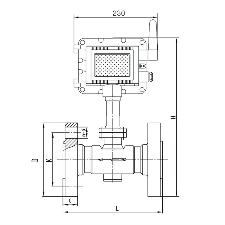
Installation Size:
Nominal Diameter(mm)
Nominal Pressure(MPa)
L
H
D
K
n-d
C
DN25
16
200
405
140
100
4-Φ18
24
25
410
150
105
4-Φ22
28
32
420
160
115
4-Φ22
34
DN32
16
200
415
155
110
4-Φ22
28
26
220
420
160
111
4-Φ26
34
32
425
175
130
4-Φ26
36
DN40
16
230
420
170
125
4-Φ22
28
25
430
185
135
4-Φ26
34
32
240
435
195
145
4-Φ26
28
DN50
16
230
445
195
145
4-Φ26
30
25
455
200
150
8-Φ26
38
32
260
460
210
160
8-Φ26
42
WE ARE HERE TO SUPPORT YOU!
Further information or a personal consultation? Our products and know-how
are there to provide solutions.