
The pressure transmitter converts the pressure of gases, liquids or steam into standard electrical signals, which are used in industrial control systems. The accuracy of this transmitter—the difference between the measured value and the actual value—is dynamic and is influenced by internal and external factors. For industry professionals, understanding these influencing factors and their mitigation strategies is crucial to ensure safe operation, product quality and economic benefits. Inaccurate pressure data can lead to operational risks, production losses and violations in various industries.
This guide details the basic factors affecting accuracy, introduces the working principle of the pressure transmitter, and provides practical solutions to help achieve optimal performance.
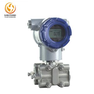
The sensing element is the core component of a pressure transmitter, responsible for converting physical pressure into a measurable electrical signal—a process at the heart of the pressure transmitter working principle. Its performance directly dictates the device’s inherent accuracy, stability, and service life. Any defect, wear, or contamination of the sensing element will introduce errors into the measurement chain, making it the primary point of failure for accuracy degradation.
The commonly used detection elements in pressure transmitters include diffusion silicon wafers, capacitive diaphragms, strain gauges, and piezoelectric crystals. These elements operate based on different physical principles, resulting in variations in their measurement accuracy. Among them, diffusion silicon elements are the most widely used in industrial applications; their working principle is based on the resistance effect: when pressure acts on a single-crystal silicon wafer, the wafer will deform, thereby changing the resistance value of the built-in resistor. This resistance change is converted into a voltage signal through a Wheatstone bridge.
During the manufacturing process of silicon wafer diffusion components, there are potential issues that may affect their accuracy: impurities in the wafer can cause non-linear changes in resistance values, thereby leading to measurement errors; uneven thickness of the wafer can result in inconsistent deformation when under pressure; long-term exposure to high temperatures or corrosive environments will reduce the resistance characteristics, causing long-term accuracy deviations. Capacitive sensors consist of a flexible diaphragm and fixed electrodes, forming a capacitor. In high humidity environments, due to diaphragm fatigue, electrode contamination, or dielectric failure, the accuracy of the sensor is prone to be affected. When the strain gauge is installed on the metal diaphragm, aging or flow of the adhesive may cause signal deviation, and the accuracy gradually decreases over time.
The quality of the sensor element also directly affects its ability to withstand harsh environments. For example, low-quality sheets may fracture under high pressure or temperature fluctuations, resulting in permanent accuracy loss; while high-precision single-crystal silicon elements have higher linearity, stability, and stronger tolerance to environmental stress.
To ensure optimal sensing element performance and maintain pressure transmitter accuracy, follow these mitigation strategies:
Select High-Quality Sensing Elements: Prioritize pressure transmitters equipped with monocrystalline silicon sensing elements, which offer better linearity and long-term stability compared to polycrystalline silicon or strain gauge alternatives. For corrosive or abrasive media, choose elements with protective coatings to prevent damage and contamination.
Match Element Type to Application: For high-precision applications, silicon diffusion components with thermal compensation function should be adopted. When used in low-pressure or vacuum environments, capacitive components can achieve higher sensitivity. While for dynamic pressure measurement, piezoelectric components need to be used as they have a faster response speed.
Regular Inspection and Maintenance: Regularly check whether the sensor components are contaminated, damaged or worn out. Use non-abrasive solvents to clean the pressure interface to remove any deposits or layers that may impede the pressure from being transmitted to the components. Replace aging or damaged parts in a timely manner; under normal operating conditions, most high-quality components can be used for 5 to 8 years.
Choose Transmitters with Stability Testing: Well-known pressure transducer manufacturers conduct rigorous stability tests on sensor components to minimize errors. For instance, Sunstrand‘s pressure transducers use single-crystal silicon components and possess precise manufacturing processes, along with built-in overvoltage protection devices, ensuring stable measurement accuracy in harsh industrial environments.
The industrial environment is often not ideal. Factors such as temperature fluctuations, vibration, humidity, and corrosive gases pose serious threats to the accuracy of pressure transmitters. These factors can alter the physical properties of the internal components, affect the normal operation of the transmitters, cause measurement errors, and may be either temporary or permanent.
Temperature is one of the most impactful environmental factors on pressure transmitter accuracy. The electrical resistance of sensing elements, signal processing circuits, and wiring varies with temperature, leading to thermal drift. For example, a diffused silicon element without temperature compensation may experience a 0.1% FS accuracy deviation for every 10℃ change in ambient temperature. In high-temperature applications, excessive heat can damage the sensing element’s piezoresistive properties or melt internal wiring, causing permanent accuracy loss. In low-temperature environments, condensation can form inside the transmitter, short-circuiting circuits or corroding components.
Temperature fluctuations also affect the measured medium itself. For example, high temperatures can cause gas expansion, increasing pressure in closed systems and leading to false readings. Conversely, low temperatures can cause liquid viscosity changes, altering pressure transmission to the sensing element.
Continuous vibration – commonly found in industrial equipment such as pumps, compressors, or rotating machinery – may cause internal components to loosen, detect membrane movement or damage to circuit connections. This could lead to unstable signals, increased noise, and long-term accuracy deviations. For instance, the movement of the bridge circuit in a silicon-based emitter due to vibration could cause resistance fluctuations, thereby introducing random errors in the measurement.
Mechanical shocks, such as those generated during equipment operation or shutdown, pipe collisions, or accidental impacts, pose even greater risks. Severe shocks may cause permanent deformation of the detection membrane, breakage of the silicon wafer, or damage to the internal circuits, resulting in irreversible loss of accuracy and even complete failure of the emitter.
Mitigation Strategies:
Select Transmitters with Temperature Compensation: Choose a pressure transmitter with built-in wide-range thermal compensation function to counteract the influence of thermal displacement. Advanced models will integrate two temperature sensors, which can simultaneously compensate for the ambient temperature and temperature changes, thus ensuring accuracy throughout the working range. Select products with shock-resistant design: look for transmitters with IP68 protection level, dual shock-absorbing housings and reinforced internal components. Install shock absorbers between the transmitter and the installation surface to reduce vibration transmission. Avoid directly installing the transmitter on vibrating pipes or near high-vibration equipment.
Protect Against Humidity and Corrosion: In humid or corrosive environments, please use sealed transmitters with anti-corrosion packaging. Install a protective housing with dehumidification function to prevent the formation of condensation water. For outdoor applications, choose waterproof transmitters with UV protection function.
Isolate from Extreme Temperatures: For high-temperature media, install a siphon loop or cooling element between the transmitter and the measurement point to reduce heat conduction. For low-temperature applications, use heated enclosures to prevent condensation and freezing.
Even the most precise pressure transducer may yield inaccurate measurement results if installed improperly. In industrial settings, pressure measurement errors due to installation or fixation mistakes can reach up to 30% of the total error, usually resulting from improper positioning, incorrect connections, or improper wiring methods. These problems can be completely avoided through appropriate training and strict adherence to the manufacturer’s instructions for use.
The mounting position of a pressure transmitter directly impacts its ability to accurately measure pressure. Common positioning errors include:
Mounting at Pipeline Bottoms: At the bottom of the horizontal pipeline, sediment, sludge or waste materials may accumulate, blocking the pressure connection points and preventing the fluid from coming into contact with the detection elements. This may result in a stagnation of pressure readings or a delay in responding to pressure changes.
Vertical Mounting on Horizontal Pipelines Without Siphon Loops: For high-temperature media, if a vertical installation without a siphon tube is adopted, the heat will directly transfer from the pipeline to the transmitter, causing thermal deformation and damaging the internal components.
Excessive Distance from Measurement Point: A long pressure tube between the transmitter and the measurement point introduces dead volume, leading to signal lag and pressure loss. This is particularly problematic for dynamic pressure measurements, where rapid response is critical.
Mounting in Turbulent Flow Zones: Installing the transmitter near elbows, valves, or pumps can expose it to turbulent flow, causing pressure fluctuations and unstable readings.
Wiring and connection errors disrupt signal transmission between the transmitter and the control system, leading to inaccurate readings, noise interference, or complete signal loss. Common issues include:
Loose or Corroded Connections: Loose wiring increases contact resistance, altering the 4-20mA analog signal. Corrosion—caused by humidity, corrosive atmospheres, or poor terminal quality—further degrades signal integrity.
Unshielded Cables in High-Interference Environments: Using unshielded cables near high-voltage equipment, motors, or inverters introduces electromagnetic interference into the signal, causing noise and fluctuations.
Incorrect Polarity: Reversing the power supply polarity can damage the transmitter’s signal processing unit, leading to permanent accuracy loss or failure.
Poor Wireless Antenna Installation: For wireless pressure transmitters, incorrect antenna positioning can lead to signal loss, data dropouts, and inaccurate readings.
Mitigation Strategies:
Follow Manufacturer Mounting Guidelines: Mount transmitters on the side of horizontal pipelines to avoid sediment accumulation. For vertical pipelines, mount the transmitter at a 45° angle to ensure proper pressure transmission. Use siphon loops for high-temperature media to isolate the transmitter from heat.
Minimize Pressure Tube Length: Keep the pressure tube between the transmitter and measurement point as short as possible to reduce dead volume and signal lag. Use smooth-bore tubes to avoid pressure loss.
Use Proper Wiring Practices: Use shielded twisted-pair cables for analog signals, and ground the shield at one end (preferably at the control system) to reduce EMI. Secure connections with anti-corrosion terminals, and verify wiring polarity before powering on the transmitter. For wireless models, position the antenna in an open area with a clear line of sight to the receiver.
Conduct Post-Installation Testing: After installation, verify the transmitter’s output against a calibrated pressure gauge to ensure accuracy. Check for signal stability and response time to confirm proper mounting and wiring.
Pressure transmitters experience gradual accuracy drift over time due to component wear, environmental impact, and medium contamination. Regular calibration and maintenance are essential to restore accuracy, extend service life, and ensure compliance with industry standards. Neglecting these practices is one of the most common reasons for accuracy degradation and costly operational issues.
Calibration involves comparing the transmitter’s measured output to a known standard pressure and adjusting the device to minimize deviations. Without regular calibration, accuracy drift can exceed the allowable range within 6-12 months. For example, a pressure transmitter used in chemical reactors with a specified accuracy of ±0.1% FS may drift by 0.3% FS after one year of operation—far exceeding the process requirement of ±0.2% FS. This drift can lead to incorrect process control decisions, product quality issues, and regulatory non-compliance.
Many plants delay calibration to avoid downtime, but the cost of unplanned downtime due to accuracy-related failures is often 10-20 times higher than the cost of scheduled calibration. Additionally, uncalibrated transmitters may fail to detect critical pressure anomalies, increasing safety risks.
Inadequate maintenance exacerbates accuracy loss and shortens the transmitter’s service life. Common maintenance oversights include:
Neglecting Pressure Port Cleaning: Sediment, buildup, or corrosion in the pressure port blocks pressure transmission to the sensing element, leading to inaccurate readings.
Ignoring Wiring and Seal Wear: Worn wiring insulation or damaged seals can cause leaks, short circuits, or EMI interference, disrupting signal transmission.
Overlooking Environmental Damage: Humidity, corrosion, or vibration can damage internal components over time, leading to gradual accuracy drift.
Mitigation Strategies:
Establish a Regular Calibration Schedule: Calibrate pressure transmitters annually for general industrial applications, and semi-annually for critical processes. Use a calibrated pressure source with an accuracy 3-5 times higher than the transmitter to ensure reliable results. For smart transmitters, use a HART communicator to adjust zero and span settings.
Implement Preventive Maintenance: Clean pressure ports monthly with non-abrasive solvents to remove sediment and buildup. Inspect wiring, terminals, and seals quarterly for wear, corrosion, or damage, and replace worn parts promptly. Check the transmitter’s housing for cracks or leaks, and ensure protective enclosures are intact.
Document Calibration and Maintenance: Maintain detailed records of calibration results, maintenance activities, and part replacements. This documentation is critical for regulatory compliance and helps identify trends in accuracy drift, allowing for proactive adjustments.
Use Manufacturer Support: Partner with pressure transmitter manufacturers that offer on-site calibration and maintenance services. Sunstrand, for example, provides trained technicians to perform on-site calibration, maintenance, and troubleshooting, ensuring optimal accuracy and minimizing downtime.
Range selection is a critical step in ensuring pressure transmitter accuracy. The range of a pressure transmitter—defined as the minimum and maximum pressure it can measure—directly impacts measurement precision, device lifespan, and system safety. A mismatched range not only reduces accuracy but also increases the risk of overpressure damage to the sensing element.
Pressure transmitter accuracy is calculated based on full scale, meaning the absolute error increases with the range. For example, a 0-10MPa transmitter with ±0.1% FS accuracy has an absolute error of 0.01MPa. If this transmitter is used to measure a pressure range of 0-1MPa, the relative error becomes 1%, which may exceed the process requirement. Conversely, using a range that is too small for the application can cause overpressure, deforming the sensing element and leading to permanent accuracy loss.
Transient pressure peaks—common in systems with pumps, valves, or compressors—also contribute to range mismatch. For example, a system with a normal working pressure of 3-5MPa may experience occasional peaks of 8MPa. Using a 0-6MPa transmitter to measure this system will result in frequent overpressure, damaging the sensing element and compromising accuracy.
To select the optimal range and maintain pressure transmitter accuracy, use the following transmitter accuracy calculation formula and steps:
Calculate Maximum Expected Pressure: Determine the normal working pressure range and the maximum transient peak pressure. Use pressure loggers to record pressure fluctuations over time to capture all extreme conditions.
Apply the Range Selection Formula: The recommended range is calculated as: Recommended Range = Maximum Expected Pressure × 1.5-2. The 1.5-2 factor provides a safety margin to accommodate transient peaks and prevent overpressure damage. For example, if the maximum expected pressure is 6MPa, a range of 0-10MPa (6×1.67) or 0-12MPa (6×2) is suitable.
Calculate Absolute Error: Use the transmitter accuracy calculation formula to verify that the absolute error meets process requirements: Absolute Error = Range × Accuracy Rating. For example, a 0-10MPa transmitter with ±0.1% FS accuracy has an absolute error of 0.01MPa. Ensure this error is within the process’s allowable tolerance.
Using a range that is too large for the application can be mitigated with smart transmitters that support dynamic range adjustment. These transmitters allow users to adjust the range digitally, balancing precision and coverage for fluctuating pressure conditions.
Mitigation Strategies:
Conduct Thorough Pressure Analysis: Use pressure loggers to record pressure data over 1-2 weeks, capturing normal operating conditions and transient peaks. This ensures you select a range that accommodates all pressure fluctuations.
Choose Smart Transmitters with Dynamic Range Adjustment: Sunstrand’s smart pressure transmitters support dynamic range adjustment, allowing users to modify the range without physical calibration. This is ideal for applications with variable pressure conditions, ensuring optimal accuracy across the operating range.
Install Pressure Relief Valves: For systems with frequent transient peaks, install pressure relief valves to protect the transmitter from overpressure damage. This extends the sensing element’s life and maintains accuracy.
Reassess Range Periodically: As process conditions change (e.g., increased production capacity), reassess the transmitter range to ensure it still meets accuracy requirements. Adjust the range or replace the transmitter if necessary.
Industrial environments are filled with sources of electromagnetic interference (EMI), such as motors, inverters, high-voltage cables, and radio frequency (RF) devices. EMI disrupts the pressure transmitter working principle by interfering with signal transmission between the transmitter and the control system, causing unstable readings, noise, or complete signal loss.
Common sources of EMI in industrial settings include:
High-Voltage Equipment: Transformers, circuit breakers, and high-voltage cables generate strong electromagnetic fields that induce noise in transmitter cables.
Inverters and Frequency Converters: These devices produce harmonic interference that disrupts analog signals (4-20mA) and digital communication.
RF Devices: Wireless communication equipment can interfere with wireless pressure transmitters, causing data dropouts and inaccurate readings.
Electrostatic Discharge (ESD): ESD from personnel or equipment can damage the transmitter’s signal processing unit, leading to permanent accuracy loss.
To protect pressure transmitters from EMI and maintain accuracy, implement the following strategies:
Use Shielded Cables and Proper Grounding: For analog transmitters, use shielded twisted-pair cables and ground the shield at one end to reduce noise induction. Avoid grounding both ends, as this creates a ground loop that amplifies EMI.
Separate Transmitter Cables from EMI Sources: Route transmitter cables at least 1 meter away from high-voltage cables, motors, and inverters. Avoid parallel routing, as this increases EMI coupling.
Install EMI Filters: Install EMI filters at the transmitter’s power input and signal output to suppress harmonic interference. For digital transmitters, use surge protectors to prevent ESD damage.
Choose EMI-Resistant Transmitters: Select pressure transmitters with electromagnetic compatibility (EMC) certification to ensure they can withstand industrial EMI levels. Sunstrand’s pressure transmitters feature EMC design with reinforced shielding, making them resistant to EMI in power plants, refineries, and other high-interference environments.
Opt for Wireless Transmitters with Anti-Interference Technology: For wireless applications, choose transmitters with LoRa spread spectrum technology, which offers superior anti-interference performance compared to WiFi or Bluetooth. Sunstrand’s SM-500 wireless pressure transmitter uses LoRa technology to deliver stable data transmission in high-EMI environments.
The quality of pressure transmitter manufacturers directly impacts the inherent accuracy, stability, and reliability of the device. Reputable manufacturers invest in R&D, rigorous testing, and high-quality materials, while low-cost manufacturers cut corners to reduce prices—resulting in poor accuracy, frequent failures, and increased long-term costs.
High-quality pressure transmitter manufacturers optimize every aspect of the pressure transmitter working principle to enhance accuracy. They use precision-machined sensing elements, advanced signal processing circuits, and rigorous quality control processes to ensure each transmitter meets its specified accuracy rating. For example, Sunstrand’s manufacturing facilities adhere to ISO 9001 quality standards, and each pressure transmitter undergoes 10+ quality tests—including stability testing, temperature compensation testing, and EMI testing—before leaving the factory.
Low-quality manufacturers, by contrast, use inferior materials, skip quality tests, and use outdated technology. This results in transmitters with high initial errors, rapid accuracy drift, and poor resistance to environmental stress. For example, a low-cost transmitter may have an initial accuracy of ±0.5% FS instead of the advertised ±0.1% FS, leading to immediate process issues.
To select a reliable pressure transmitter manufacturer and ensure long-term accuracy, consider the following criteria:
Quality Certifications: Prioritize manufacturers with global certifications, such as CE, ATEX/IECEx, FDA. These certifications confirm compliance with international safety and quality standards.
R&D Capabilities: Look for manufacturers with a strong R&D team and patents in sensing technology, temperature compensation, or EMI resistance. Reputable manufacturers invest 5-10% of revenue in R&D to improve the pressure transmitter working principle and enhance accuracy.
Quality Control Processes: Inquire about the manufacturer’s quality control processes, including testing procedures, inspection standards, and failure rates. Top manufacturers provide detailed quality reports and offer warranties of 2-5 years, indicating confidence in their products.
After-Sales Support: Choose manufacturers with comprehensive after-sales support, including on-site calibration, maintenance, technical support, and spare parts availability. A reliable manufacturer should offer 24/7 technical support to resolve issues quickly.
Industry Experience: Select manufacturers with 10+ years of experience in the industrial sensor industry. Sunstrand, for example, has 20+ years of experience designing and manufacturing pressure transmitters for harsh industrial environments, with a proven track record of delivering reliable accuracy.
|
Key Factor |
Core Impact on Accuracy |
Mitigation Strategies |
|
Sensing Element Performance |
Non-linear errors, drift, or permanent damage due to material defects, fatigue, or contamination; directly impacts the pressure transmitter working principle. |
Choose monocrystalline silicon elements; use protective coatings for harsh media; inspect and replace aging elements regularly; select transmitters with stability testing. |
|
Environmental Conditions |
Temperature drift, component loosening, circuit short-circuit, or corrosion caused by temperature fluctuations, vibration, humidity, or EMI. |
Select transmitters with wide-range temperature compensation and IP68 protection; install vibration dampeners; use shielded cables; protect against humidity/corrosion. |
|
Installation & Mounting Errors |
Signal lag, pressure loss, noise interference, or blocked pressure ports due to incorrect positioning, wiring, or connection. |
Follow manufacturer guidelines; mount on pipeline sides (avoid bottoms); use shielded twisted-pair cables; conduct post-installation testing. |
|
Calibration & Maintenance Practices |
Gradual drift exceeding allowable range due to lack of calibration; accelerated wear from inadequate maintenance. |
Calibrate annually (semi-annually for critical processes); clean pressure ports monthly; inspect wiring/seals quarterly; document all activities. |
|
Transmitter Range Mismatch |
Increased relative error (over-range) or permanent damage (under-range); transient peaks cause accuracy loss. |
Calculate range as 1.5-2× maximum expected pressure; use smart transmitters with dynamic range adjustment; install pressure relief valves. |
|
Electromagnetic Interference (EMI) |
Signal instability, noise induction, or data dropouts disrupting analog/digital signal transmission. |
Use shielded cables (single-end grounding); separate from high-voltage equipment; install EMI filters; choose EMC-certified transmitters. |
|
Quality of Pressure Transmitter Manufacturers |
Initial errors, rapid drift, or poor environmental resistance due to substandard materials, skipped testing, or outdated technology. |
Select ISO 9001-certified manufacturers with global certifications; prioritize R&D capabilities and 2-5 year warranties; verify after-sales support. |
Sunstrand, a leading name among pressure transmitter manufacturers, designs and manufactures high-precision pressure transmitters that deliver reliable accuracy in the most challenging industrial environments. The following cases showcase how Sunstrand’s technology addresses key accuracy factors and provides tangible value to clients.
A large petrochemical refinery in the Middle East needed to measure pressure in reactors operating at 280℃ and 8MPa, with a required accuracy of ±0.1% FS. Previous pressure transmitters from a low-cost manufacturer failed within 6 months due to thermal drift and corrosion, leading to product quality issues and unplanned downtime.
Sunstrand provided ST-300 pressure transmitters, equipped with monocrystalline silicon sensing elements with Hastelloy protective coatings, double-layer temperature compensation, and reinforced shock absorption housings. The transmitters were calibrated on-site using a traceable pressure standard, and Sunstrand’s technicians provided installation guidance to ensure proper mounting and wiring.
After 12 months of continuous operation, the ST-300 transmitters maintained an accuracy of ±0.08% FS—well within the client’s requirement. The refinery reported an 8% reduction in product scrap rate, a 30% decrease in unplanned downtime, and annual cost savings of $2.4 million. The transmitters’ corrosion resistance and temperature compensation capabilities eliminated accuracy drift, even in the harsh high-temperature, high-pressure environment.
A thermal power plant in Southeast Asia experienced frequent signal fluctuations in its pressure transmitters due to EMI from inverters, high-voltage cables, and RF communication equipment in the control room. These fluctuations caused inaccurate pressure readings, leading to inefficient boiler operation and increased energy consumption.
Sunstrand deployed SM-500 wireless pressure transmitters, featuring LoRa spread spectrum technology, EMC design, and reinforced shielding. The transmitters were paired with high-gain antennas positioned to avoid EMI sources, and Sunstrand’s technical team optimized the wireless network to ensure stable data transmission.
The SM-500 transmitters delivered consistent accuracy of ±0.075% FS, eliminating signal fluctuations and ensuring precise boiler pressure control. The power plant reduced energy consumption by 5% and improved operational efficiency by 15%. The wireless design also reduced wiring costs by 70% compared to traditional analog transmitters.
Pressure transmitter accuracy is influenced by a complex interplay of factors, from the performance of the sensing element and environmental conditions to installation practices, calibration schedules, range selection, EMI, and the quality of pressure transmitter manufacturers. Mastering the pressure transmitter working principle, applying the transmitter accuracy calculation formula correctly, and implementing targeted mitigation strategies are essential to maintaining optimal accuracy, ensuring operational safety, and maximizing profitability.
By prioritizing high-quality sensing elements, selecting transmitters designed for your specific environment, following proper installation and calibration practices, choosing the right range, mitigating EMI, and partnering with reliable pressure transmitter manufacturers like Sunstrand, you can avoid accuracy pitfalls and ensure consistent, reliable pressure measurement. Sunstrand’s pressure transmitters integrate advanced technology, rigorous quality control, and comprehensive after-sales support, delivering the accuracy and reliability needed to thrive in today’s complex industrial landscape.
As industrial processes become increasingly automated and regulated, the demand for high-precision pressure transmitters will continue to grow. By staying informed about the factors affecting accuracy and investing in the right equipment and practices, you can position your operation for long-term success.
Q1: What is the acceptable accuracy range for industrial pressure transmitters?
A:It depends on the application: ±0.075% FS to ±0.1% FS for high-precision scenarios; ±0.25% FS to ±0.5% FS for general industrial use (water treatment, HVAC); and ±1.0% FS or higher for non-critical applications.
Q2: Can I calibrate a pressure transmitter on-site, or do I need to send it to a lab?
A:Most pressure transmitters can be calibrated on-site using a calibrated pressure source, signal tester, and HART communicator. On-site calibration minimizes downtime and ensures accuracy under actual operating conditions. For high-precision transmitters or regulatory compliance, lab calibration with a traceable standard may be required.
Q3: How often should I replace a pressure transmitter to maintain accuracy?
A:High-quality pressure transmitters have a service life of 5-8 years under normal operating conditions. However, this varies based on the environment, maintenance practices, and application. If accuracy drift exceeds the allowable range despite calibration, or if the transmitter experiences frequent failures, it may be time to replace it.
Q4: Can pressure transmitter accuracy be affected by the viscosity of the measured medium?
A:Yes. Viscous media can adhere to the sensing element or pressure port, blocking pressure transmission and causing inaccurate readings. Mitigate this by using transmitters with large-diameter pressure ports, installing filters or separators, and cleaning pressure ports regularly.
Q5: What’s the difference between static and dynamic pressure accuracy?
A:Static accuracy refers to performance under stable pressure conditions (e.g., tank pressure), while dynamic accuracy applies to fluctuating pressure. For dynamic scenarios, choose transmitters with fast response times (≤50ms) and low hysteresis to ensure accurate measurement of rapid pressure changes.
Q6: How does overpressure affect a transmitter’s accuracy?
A:Exceeding the transmitter’s rated pressure (even temporarily) can deform the sensing diaphragm, damage internal components, or alter the piezoresistive properties of the element—leading to permanent accuracy drift or complete failure. Opt for transmitters with overpressure protection and install pressure relief valves in high-surge systems.
Q7: Can humidity impact pressure transmitter accuracy?
A:Yes. High humidity can cause condensation in unprotected transmitters, short-circuiting internal circuits or corroding components. Low humidity can lead to electrostatic discharge damage. Choose transmitters with IP65+ protection ratings and sealed housings, and use desiccants in humid environments.
Q8: Is there a way to improve the accuracy of an existing pressure transmitter?
A:Yes. Recalibrate the device using a traceable standard, clean pressure ports and sensing elements to remove buildup, check and tighten wiring connections, adjust the mounting position if incorrect, and replace worn parts. For aging transmitters, upgrading to a smart model with dynamic range adjustment can also improve accuracy.
Q9: Do pressure transmitters need temperature compensation for all applications?
A:Nearly all industrial applications require temperature compensation. Even small temperature fluctuations (±5℃) can cause noticeable drift. Transmitters with built-in wide-range temperature compensation are recommended for consistent accuracy, especially in high-temperature or low-temperature environments.
Q10: How to verify if a pressure transmitter’s accuracy meets process requirements?
A:Calculate the maximum allowable absolute error based on process needs , then compare it to the transmitter’s specified error. Conduct on-site calibration with a traceable standard to confirm real-world performance matches specifications. Monitor accuracy over time with data logging to identify drift trends.
Q11: Are wireless pressure transmitters as accurate as wired models?
A:Yes. Modern wireless pressure transmitters offer the same accuracy as wired models, with ±0.075% FS precision. Advanced anti-interference technology ensures stable data transmission, making them ideal for remote or hard-to-wire locations without compromising accuracy.
Q12: What role does the pressure transmitter’s output signal type play in accuracy?
A:Analog signals are less susceptible to noise than voltage signals and offer longer transmission distances, making them more accurate for industrial applications. Digital signals provide additional data and allow for remote calibration, improving accuracy and operational efficiency. Choose the signal type based on your control system and application needs.