
In industrial automation systems, Pressure Transmitter serve as critical components that convert pressure signals into standardized electrical signals for precise monitoring and control of production processes. The accuracy of pressure transmitter range setting directly determines the reliability of pressure measurement—an improperly calculated range may lead to inaccurate data, equipment malfunctions, or even safety hazards in high-risk scenarios like chemical reactions or steam boiler operations.
This blog will systematically elaborate on the basics of Pressure Transmitter, including pressure transmitter working principle and pressure transmitter input output, break down 8 key steps for range calculation discuss turndown ratio and pressure transmitter accuracy issues, and share practical applications and industrial cases, providing a complete guide for engineers and technical personnel engaged in industrial automation.

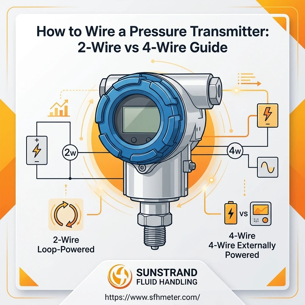
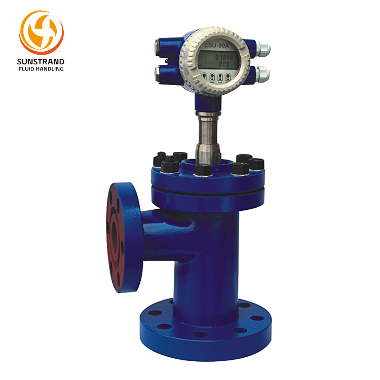
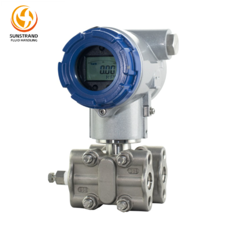
A Pressure Transmitter is a device that converts the pressure of a measured medium (gas, liquid, or vapor) into a measurable electrical signal. Its core pressure transmitter working principle involves the pressure-sensitive element deforming under the action of pressure; this deformation is then converted into an electrical signal through a conversion circuit, which is further amplified and standardized to form the pressure transmitter input output signal that is easy to transmit and process.
Key concepts related to pressure transmitter range calculation include:
Measured pressure: The actual pressure value of the medium that needs to be monitored in the process.
Pressure transmitter range: The interval between the lower limit (LL) and upper limit (UL) of the pressure that the transmitter can measure, i.e., transmitter span = UL – LL.
Benchmark pressure: Common benchmarks include gauge pressure (relative to atmospheric pressure), absolute pressure, and differential pressure. Understanding these basics is the premise for accurate calculation of pressure transmitter range and how to calculate calibration range for pressure transmitter.
Range calculation is a rigorous process that requires combining process parameters, safety requirements, and equipment performance. The following 8 steps will help you complete the calculation accurately and efficiently.
First, determine the type of pressure to be measured and its benchmark, as this directly affects the selection of calculation formulas and parameters. For example:
Gauge pressure (G): Used when measuring the pressure relative to atmospheric pressure, such as the pressure in a water supply pipeline. The lower limit is usually atmospheric pressure (0 G).
Absolute pressure (A): Required for scenarios where the pressure relative to absolute vacuum needs to be measured, such as vacuum drying processes. The lower limit is 0 absolute pressure.
Differential pressure (DP): Used to measure the pressure difference between two points, such as flow measurement using an orifice plate or level measurement in a closed tank. At this point, it is necessary to clarify the high-pressure (HP) and low-pressure (LP) sides.
Confirming the benchmark avoids fundamental errors in subsequent calculations. For instance, using a gauge pressure transmitter to measure absolute pressure will result in a measurement deviation equal to atmospheric pressure.
Gather key process parameters related to pressure measurement, including:
Normal operating pressure (Pn): The pressure value of the medium during stable production.
Maximum operating pressure (Pmax): The highest pressure that may occur during normal process fluctuations.
Minimum operating pressure (Pmin): The lowest pressure that may occur during normal operation.
Process medium properties: Such as viscosity, corrosiveness, and temperature, which indirectly affect the selection of safety margins (e.g., high-temperature media may cause pressure fluctuations).
These parameters can be obtained from process flow diagrams (PFD), piping and instrumentation diagrams (P&ID), or on-site process tests. It is crucial to ensure the accuracy of these data, as they are the basis for calculating the preliminary range.
Based on the maximum operating pressure (Pmax), calculate the preliminary upper limit of the transmitter range. The preliminary upper limit (UL_pre) should be greater than or equal to Pmax to ensure that the transmitter can cover the maximum pressure during normal operation. The basic formula is:
UL_pre ≥ Pmax
For example, if the maximum operating pressure of a chemical reactor is 1.2 MPa (gauge pressure), the preliminary upper limit should be at least 1.2 MPa.
In industrial processes, transient peak pressures may occur due to sudden changes in process conditions. To avoid the transmitter being overloaded and damaged, a safety margin must be added to the preliminary upper limit. The safety margin (SM) is usually 10%-50% of Pmax, depending on the process risk level:
Low-risk processes (e.g., ordinary water supply): SM = 10%-20%
Medium-risk processes (e.g., general chemical reactions): SM = 20%-30%
High-risk processes (e.g., explosive gas reactions): SM = 30%-50%
The formula for the upper limit after adding the safety margin is:
UL = UL_pre + (Pmax × SM)
Continuing with the previous example: If Pmax = 1.2 MPa and SM = 25%, then UL = 1.2 + (1.2 × 0.25) = 1.5 MPa.
The lower limit (LL) of the range is determined by the pressure type and minimum operating pressure:
For gauge pressure measurement: LL is usually 0 G (atmospheric pressure), unless the process may have negative pressure (vacuum), in which case LL should be less than or equal to the minimum negative pressure.
For absolute pressure measurement: LL = 0 A (absolute vacuum).
For differential pressure measurement: LL is the minimum differential pressure that may occur, which could be negative (if the LP side pressure is higher than the HP side).
Verify that LL is less than or equal to Pmin to ensure that the transmitter can accurately measure the pressure at the minimum operating condition. For example, if a process may have a minimum gauge pressure of -0.1 MPa (slight vacuum), the LL of the transmitter should be set to -0.1 MPa or lower.
The transmitter span (S) of the pressure transmitter range is the difference between the upper limit and the lower limit, which reflects the measurement range of the Pressure Transmitter. The formula is:
S = UL – LL
Using the previous example where UL = 1.5 MPa and LL = 0 MPa (gauge pressure), the transmitter span S = 1.5 – 0 = 1.5 MPa. The transmitter span is an important parameter for transmitter calibration, as it determines the linear relationship between the measured pressure and the pressure transmitter input output signal.
Different industrial processes have different requirements for pressure transmitter accuracy. After calculating the initial pressure transmitter range, recheck whether the range meets the pressure transmitter accuracy requirements. The pressure transmitter accuracy is usually expressed as a percentage of the transmitter span. The allowable error (E_allow) is calculated using the transmitter accuracy calculation formula:
E_allow = S × Pressure Transmitter Accuracy
Verify that the allowable error is less than or equal to the maximum allowable error required by the process (E_process). If E_allow > E_process, the pressure transmitter range needs to be adjusted (e.g., reducing the transmitter span by lowering the upper limit appropriately, provided that it still covers Pmax + SM). For example, if the process requires a maximum allowable error of ±0.015 MPa and the pressure transmitter accuracy is ±0.1% of span, then S must be ≤ 0.015 / 0.001 = 15 MPa. The previously calculated transmitter span of 1.5 MPa meets this requirement.
Industrial pressure transmitters have standard range series (e.g., 0-1 MPa, 0-1.6 MPa, 0-2.5 MPa) to facilitate production, selection, and replacement. After completing the above calculations, match the calculated UL and LL to the nearest standard range. It should be noted that the standard upper limit must be greater than or equal to the calculated UL, and the standard lower limit must be less than or equal to the calculated LL. For example, if the calculated UL is 1.5 MPa, the nearest standard upper limit is 1.6 MPa, so the final range is set to 0-1.6 MPa (gauge pressure).
|
Step Number |
Core Task |
Key Points |
|
1 |
Clarify Pressure Type & Benchmark |
Distinguish gauge/absolute/differential pressure; confirm measurement benchmark to avoid fundamental errors |
|
2 |
Collect Core Process Parameters |
Gather Pn, Pmax, Pmin and medium properties; ensure data accuracy from PFD/P&ID or on-site tests |
|
3 |
Preliminary Upper Limit Calculation |
UL_pre ≥ Pmax to cover maximum normal operating pressure |
|
4 |
Add Safety Margin for Peak Pressure |
SM: 10%-50% based on risk level; UL = UL_pre + (Pmax × SM) |
|
5 |
Verify Lower Limit Accuracy |
LL ≤ Pmin; set based on pressure type (0 G for gauge, 0 A for absolute) |
|
6 |
Calculate Range Span |
Span = UL – LL; determines linear relationship with input-output signal |
|
7 |
Recheck with Accuracy Requirements |
Use transmitter accuracy calculation formula; ensure E_allow ≤ E_process |
|
8 |
Match Standard Range Series |
Select nearest standard range; ensure standard UL ≥ calculated UL and standard LL ≤ calculated LL |
What is turndown ratio in pressure transmitter? Turndown ratio (TR) refers to the ratio of the maximum measurable range to the minimum measurable range of a Pressure Transmitter while maintaining pressure transmitter accuracy. It is expressed as:
TR = Maximum Span / Minimum Span
For example, a Pressure Transmitter with a standard pressure transmitter range of 0-10 MPa and a turndown ratio of 10:1 can be adjusted to a minimum range of 0-1 MPa while ensuring pressure transmitter accuracy. The turndown ratio is crucial for processes with large pressure fluctuations, as it allows a single Pressure Transmitter to cover multiple operating conditions, reducing equipment costs. When selecting a Pressure Transmitter, the turndown ratio should be matched with the process pressure fluctuation range—if the fluctuation range is large, a Pressure Transmitter with a higher turndown ratio should be chosen.
The pressure transmitter accuracy is affected by the turndown ratio. When the Pressure Transmitter is operated at a reduced range (i.e., using a smaller transmitter span than the maximum span), the actual pressure transmitter accuracy will decrease. The transmitter accuracy calculation formula for calculating the actual accuracy (Acc_actual) at a reduced span is:
Acc_actual = Acc_nominal × (Maximum Span / Reduced Span)
Where Acc_nominal is the nominal pressure transmitter accuracy provided by the manufacturer (based on the maximum span). For example, a Pressure Transmitter with a nominal pressure transmitter accuracy of ±0.1% of maximum span (10 MPa) and a turndown ratio of 10:1 will have an actual pressure transmitter accuracy of ±0.1% × (10 / 1) = ±1.0% when used at a reduced transmitter span of 1 MPa. This indicates that when using a Pressure Transmitter at a reduced range, it is necessary to recheck whether the actual pressure transmitter accuracy meets the process requirements.
The calculated pressure transmitter range is the basis for how to calculate calibration range for pressure transmitter and subsequent transmitter calibration. The process of how to calibrate a pressure transmitter typically includes the following steps:
1. Connect the pressure calibrator to the Pressure Transmitter’s pressure port.
2. Set the Pressure Transmitter’s range parameters (UL and LL) according to the calculated pressure transmitter range values.
3. Apply zero pressure (LL) and adjust the zero point so that the pressure transmitter input output signal is 4 mA.
4. Apply full-scale pressure (UL) and adjust the transmitter span so that the pressure transmitter input output signal is 20 mA.
5. Check the linearity by applying 25%, 50%, and 75% of the transmitter span pressure, ensuring that the pressure transmitter input output signal deviation is within the allowable error range based on pressure transmitter accuracy.
Calibration should be performed regularly to maintain pressure transmitter accuracy, especially in harsh industrial environments.
A multimeter can be used to quickly test whether the Pressure Transmitter’s output signal matches the calculated pressure transmitter range, which is a key part of how to check pressure transmitter with multimeter. The steps for how to check pressure transmitter with multimeter are:
1. Set the multimeter to the current measurement range (mA).
2. Connect the multimeter in series to the Pressure Transmitter’s output circuit (between the Pressure Transmitter and the controller).
3. Apply zero pressure: The multimeter should display 4 mA (±allowable error based on pressure transmitter accuracy).
4. Apply full-scale pressure: The multimeter should display 20 mA (±allowable error based on pressure transmitter accuracy).
5. Apply intermediate pressure: The pressure transmitter input output signal should be 12 mA (±allowable error based on pressure transmitter accuracy).
If the measured signal deviates significantly from the theoretical value, the Pressure Transmitter needs to be recalibrated (following how to calibrate a pressure transmitter steps) or inspected for faults (e.g., damaged pressure-sensitive elements).
A chemical plant uses a reactor for the synthesis of ethylene glycol. The process requirements for the Pressure Transmitter are:
Medium: Mixed gas-liquid reactants (corrosive, high-temperature).
Normal operating pressure (Pn): 2.0 MPa (gauge pressure).
Maximum operating pressure (Pmax): 2.5 MPa (gauge pressure).
Minimum operating pressure (Pmin): 1.8 MPa (gauge pressure).
Process risk level: High (possible reaction surge, leading to sudden pressure peaks).
Pressure transmitter accuracy requirement: Allowable error ≤ ±0.025 MPa.
The task is to calculate the pressure transmitter range and determine how to calculate calibration range for pressure transmitter for this reactor.
In this case, a 30% safety margin is selected because the reactor is a high-risk process. Chemical reaction surges may cause transient pressure peaks that exceed Pmax. A higher safety margin ensures that the Pressure Transmitter will not be overloaded by these peaks. Additionally, the standard pressure transmitter range is set to 0-4.0 MPa instead of the calculated 3.25 MPa because standard pressure transmitter range series are more readily available in the market, and the larger transmitter span still meets the pressure transmitter accuracy requirement (using the transmitter accuracy calculation formula, E_allow = 4.0 × 0.001 = 0.004 MPa ≤ 0.025 MPa). The turndown ratio of the selected Pressure Transmitter is 10:1, so it can be adjusted to a more precise pressure transmitter range if needed, further improving pressure transmitter accuracy. When performing how to calibrate a pressure transmitter procedures for this device, the calibration range should align with the adjusted pressure transmitter range to ensure measurement reliability.
Accurate pressure transmitter range calculation is a key link in ensuring the stability and safety of industrial processes. By following the 8 steps of clarifying pressure type, collecting process parameters, calculating preliminary upper limit, adding safety margin, verifying lower limit, calculating transmitter span, rechecking pressure transmitter accuracy, and matching standard pressure transmitter range, engineers can determine the optimal Pressure Transmitter range and answer how to calculate calibration range for pressure transmitter. Meanwhile, understanding what is turndown ratio in pressure transmitter and its relationship with pressure transmitter accuracy helps in selecting appropriate Pressure Transmitter for processes with large pressure fluctuations. Practical operations such as how to calibration of pressure transmitter, how to calibrate a pressure transmitter, and how to check pressure transmitter with multimeter based on the calculated pressure transmitter range ensure the reliability of measurement data.
Additionally, grasping pressure transmitter working principle and pressure transmitter input output characteristics aids in better troubleshooting and maintenance. The industrial case of the chemical reactor demonstrates the application of these steps and concepts in high-risk scenarios, providing a reference for similar projects. For reliable pressure measurement solutions that adhere to these scientific principles, you can visit Sunstrand‘s official website at https://www.sfhmeter.com/ to explore professional products and technical support. In summary, scientific pressure transmitter range calculation, rational Pressure Transmitter selection, and standardized calibration and testing are essential for improving the level of industrial automation and ensuring production safety.
Q1: What is the difference between gauge pressure and absolute pressure in range calculation?
A1: The pressure gauge measures based on atmospheric pressure, so its minimum value is approximately 0G. Absolute pressure is relative to absolute vacuum. Incorrect reference values may cause deviations between the measured values and atm (approximately 0.1 MPa).
Q2: How to determine the safety margin for different processes?
A2: The safety margin is determined by the process risk level: low-risk (10%-20%), medium-risk (20%-30%), and high-risk (30%-50%). For processes with frequent pressure fluctuations or potential explosion risks, a higher safety margin should be selected. Additionally, reference the manufacturer’s recommendations and industry standards.
Q3: Can a transmitter with a larger range be used for small-pressure measurement?
A3: Yes, but it is necessary to consider the turndown ratio. Using a transmitter with a larger range for small-pressure measurement means operating at a reduced span, which will decrease the actual accuracy. Ensure that the actual accuracy after reducing the span meets the process requirements. For example, a transmitter with a 10:1 turndown ratio can be used for small-pressure measurement within 1/10 of its maximum span.
Q4: How often should the pressure transmitter range be recalibrated?
A4: It is recommended that general industrial processes be recalibrated once every quarter. For processes with higher risks, they should be recalibrated once a month. In addition, when measuring, maintaining equipment or conditions, recalibration must be carried out immediately.