
Accurate temperature measurement is critical in industries from petrochemical plants to automated labs. Even minor deviations can affect safety and efficiency. Temperature Transmitters convert sensor signals into precise readings, and the Sunstrand Temperature Transmitter stands out for its accuracy and versatility. Designed with multiple sensing elements, it is ideal for measuring non-precipitating liquids in automation, lab monitoring, and equipment matching. Regular calibration ensures reliable performance. In this article, we’ll explore how to calibrate a temperature transmitter with clear procedures, formulas, and expert tips.
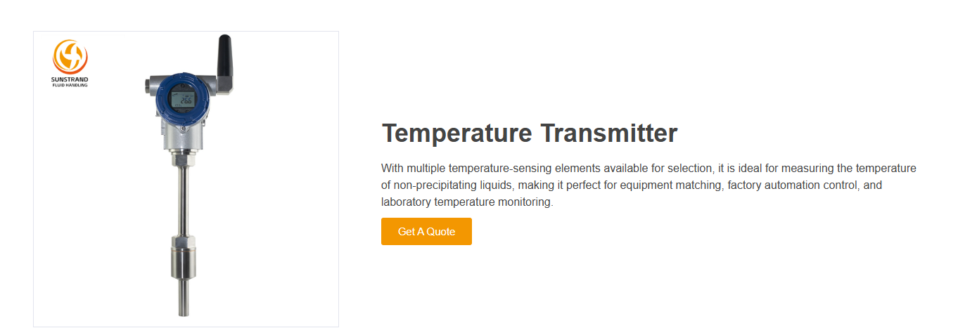
A Temperature Transmitter is an instrument that converts the signal from a temperature sensor—such as a thermocouple or RTD—into a standardized output, typically 4–20 mA or a digital communication signal.
In simple terms, it acts as a bridge between the sensor and the control system, ensuring that temperature readings remain stable even over long distances.
Key functions include:
Converting sensor input into a standardized electrical signal
Compensating for sensor and ambient variations
Sending accurate temperature data to PLCs or control systems
Understanding what is a temperature transmitter helps in performing accurate calibration and troubleshooting.
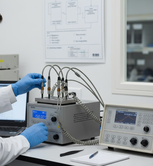
Calibrating a Temperature Transmitter is both an art and a science. It requires a clear understanding of how the transmitter functions, careful planning, and a structured workflow to ensure reliable and traceable results. Whether you are working in a refinery, food processing plant, or laboratory, a systematic approach guarantees consistency and compliance with industry standards.
Before you start, determine why you are calibrating. There are two main objectives:
Verification: Checking if the transmitter’s readings are within acceptable error limits without making any adjustments.
Adjustment: Fine-tuning or correcting the transmitter output if deviations exceed the allowed tolerance.
Depending on your objective, the calibration may be in-situ (on-site) or in-lab using controlled conditions.
There are three common approaches to temperature transmitter calibration:
Full System Calibration (Sensor + Transmitter):
The most accurate method. Both the temperature sensor (RTD or thermocouple) and the transmitter are calibrated together. This simulates actual operating conditions and accounts for sensor errors.
Transmitter-Only Calibration (Electronic Simulation):
Used when removing the transmitter from the process. A temperature simulator injects electrical signals equivalent to temperature inputs, and the output current (4–20 mA) is verified.
Loop Calibration:
Includes the transmitter and the control system loop (PLC/DCS). Ensures the entire measurement and signal transmission chain is functioning accurately.
Every calibration must be traceable to a national or international standard (e.g., NIST, ISO 17025).
Use a reference thermometer or calibrator with at least four times better accuracy than the transmitter under test.
Temperature calibration is highly sensitive to environmental changes. Ensure:
Ambient temperature remains stable (±1°C or less).
No drafts, vibrations, or direct sunlight on the equipment.
The transmitter and reference probe are both in thermal equilibrium before readings.
To verify accuracy and linearity, use at least five calibration points evenly distributed across the measuring range, such as:
0% (Lower Range Limit)
25%
50%
75%
100% (Upper Range Limit)
If deviations exceed the specified tolerance, perform necessary zero and span adjustments. After that, repeat the calibration cycle and record “As Left” data to confirm accuracy.
A disciplined, step-by-step approach like this minimizes uncertainty and ensures that your Temperature Transmitter provides precise and stable output over its operational life.
The temperature transmitter calibration formula allows you to verify expected current output during calibration:
I=4+(T−Tmin)×16Tmax−TminI = 4 + \frac{(T – T_{min}) \times 16}{T_{max} – T_{min}}
Where:
I = Output current (mA)
T = Actual temperature (°C)
Tmin = Lower range
Tmax = Upper range
Example:
If the range is 0–100°C and the measured temperature is 50°C:
I=4+(50−0)×16100−0=12 mAI = 4 + \frac{(50 – 0) \times 16}{100 – 0} = 12 \text{ mA}
This equation ensures that the transmitter output corresponds precisely to the reference input—an essential part of the temperature transmitter calibration procedure.
Before you start calibrating, keep these important considerations in mind:
Stabilization: Allow the transmitter and sensor to reach ambient temperature before calibration.
Clean Connections: Ensure terminals and connectors are free from corrosion and dirt.
Power Supply Check: Use a regulated 24V DC supply for accurate results.
Sensor Matching: Verify that the transmitter configuration (RTD, thermocouple type) matches the sensor used.
Safety: Follow lockout/tagout procedures before disconnecting process instruments.
Documentation: Record “As Found” data before any adjustments for traceability.
Following these steps minimizes error sources and ensures a safe calibration environment.
A successful calibration depends on using the right instruments. Below are essential tools for calibrating a temperature transmitter:
| Tool | Function |
|---|---|
| Temperature calibrator (dry block or bath) | Generates stable, known temperature points |
| Reference thermometer | Verifies the true temperature value |
| Multimeter or loop calibrator | Measures the 4–20 mA output signal |
| 24V DC power supply | Powers the transmitter circuit |
| HART communicator or configuration software | For smart transmitter trimming |
| Wiring and documentation tools | For connection and data logging |
Tip: Always use reference equipment that’s at least four times more accurate than the transmitter under test.
The temperature transmitter calibration procedure involves systematic testing, adjustment, and verification of the transmitter’s input-output relationship. The goal is to ensure that the output signal (usually 4–20 mA) accurately represents the measured temperature according to the calibration range. Here’s a detailed, professional-grade calibration procedure suitable for both analog and smart transmitters (like the Sunstrand Temperature Transmitter).
Isolate the Transmitter
Shut down the process and ensure no active signals are present. Tag and lockout equipment if required by plant safety standards.
Review Manufacturer’s Specifications
Note the transmitter’s model, sensor type (RTD or thermocouple), input range, and output type. Confirm whether it’s configured for 2-wire, 3-wire, or 4-wire connection.
Allow Stabilization
Let the transmitter and sensors acclimate to ambient conditions for at least 15–30 minutes before starting.
You’ll need the following tools:
Temperature calibrator or dry-block furnace
Reference thermometer or probe
24V DC power supply
Digital multimeter or loop calibrator (for measuring mA)
HART communicator or configuration software (for smart transmitters)
Connection Steps:
Connect the transmitter input terminals to the calibrator or reference sensor.
Power the transmitter with a 24V DC source.
Connect the output loop to a multimeter to measure the 4–20 mA signal.
If it’s a smart transmitter, connect the HART communicator to access configuration settings.
Perform calibration across the full measurement range, typically using five evenly spaced points (0%, 25%, 50%, 75%, 100%).
Example:
If the transmitter range is 0°C to 200°C:
0°C → 4 mA
50°C → 8 mA
100°C → 12 mA
150°C → 16 mA
200°C → 20 mA
At each point:
Apply the known temperature (using calibrator or simulator).
Wait until the reading stabilizes.
Record both the reference temperature and transmitter output current.
Use the temperature transmitter calibration formula:
I=4+(T−Tmin)×16Tmax−TminI = 4 + \frac{(T – T_{min}) \times 16}{T_{max} – T_{min}}
Compare the actual current output with the expected theoretical output.
Calculate the deviation in percentage or mA.
If the deviation exceeds the allowed tolerance (e.g., ±0.1% of span), adjustment is required.
Depending on the transmitter type:
Analog Transmitter:
Use the Zero screw to set the 4 mA point and the Span screw to adjust the 20 mA point.
After adjusting, recheck intermediate points to ensure linearity.
Smart Transmitter (e.g., Sunstrand Temperature Transmitter):
Use a HART communicator or software to perform:
Sensor trim: Aligns transmitter input with reference sensor values.
Output trim: Aligns 4–20 mA output to match reference calibration.
Tip: Always trim the sensor first, then the output.
Re-run the calibration points and confirm the transmitter’s output is within specification.
Record all results, including:
Reference temperatures
Measured output (As Found / As Left)
Date, technician name, and reference equipment used
Label the transmitter with a calibration tag showing date, next due date, and technician initials.
Once calibration is complete:
Reinstall the transmitter in its original process location.
Perform a loop check by applying known inputs and verifying that the control system (PLC or DCS) displays the correct temperature.
Ensure wiring and grounding are properly restored.
This comprehensive process ensures that your calibrate temperature transmitter operation achieves accuracy, traceability, and long-term reliability.
Regular calibration of temperature transmitters is essential for maintaining process reliability, safety, and compliance.
Here’s why calibration matters:
Accuracy: Ensures correct temperature data for precise process control.
Compliance: Meets quality standards such as ISO 9001 or IEC 17025.
Efficiency: Prevents waste and energy loss from incorrect readings.
Safety: Detects faulty sensors before they cause process failures.
Traceability: Provides auditable calibration records for regulatory inspections.
In industries like petroleum, chemical, and environmental protection, temperature calibration ensures product quality and operational safety.
Regular calibration keeps Temperature Transmitters accurate and reliable, safeguarding product quality and process efficiency. The Sunstrand Temperature Transmitter delivers precision and stability for automation, laboratory monitoring, and industrial applications. Ensure consistent performance by following proper calibration procedures. Discover Sunstrand’s full range of Temperature Transmitters to enhance your process control with accuracy and reliability.