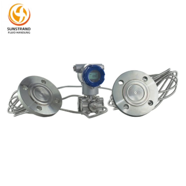

In today’s industrial automation and process control systems, Sunstrand stands out as a trusted name in precision measurement technology. Accurate temperature monitoring is vital for maintaining efficiency, product quality, and safety — and that’s where the Sunstrand Temperature Transmitter delivers exceptional performance.Engineered by Sunstrand Fluid Handling Co., Ltd., this transmitter converts temperature sensor signals into stable, standardized outputs for easy integration with control systems. With multiple sensing elements available, it provides reliable measurement for non-precipitating liquids, making it ideal for equipment matching, factory automation, and laboratory temperature monitoring. Designed for long-term stability and accuracy, Sunstrand ensures dependable temperature control across diverse industrial applications.
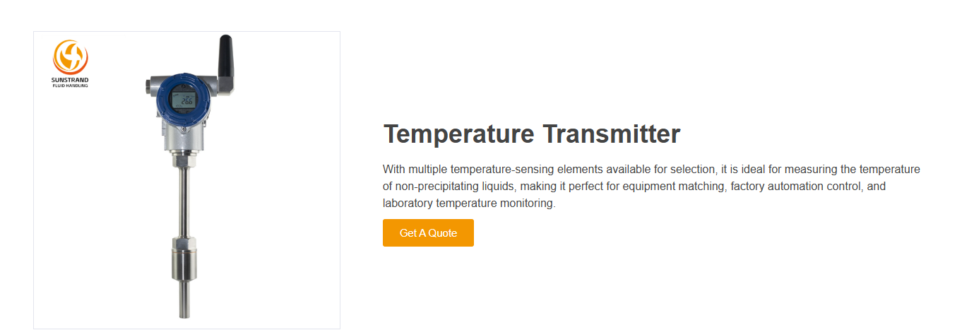
A temperature transmitter is an electronic device that receives a signal from a temperature sensor—such as a thermocouple or an RTD (Resistance Temperature Detector)—and converts it into a standard output signal (usually 4–20 mA or digital). This standardized signal can then be transmitted over long distances to monitoring or control systems without signal degradation.In simpler terms, if the sensor is the “eye” detecting temperature, the transmitter is the “messenger” that delivers this information accurately to the control center.
| Function | Description | Technical Details / Working Principle | Industrial Benefit / Application |
|---|---|---|---|
| Signal Conversion | Converts the weak electrical signal from the temperature sensor (RTD or thermocouple) into a standardized output such as 4–20 mA or digital communication. | RTD resistance or thermocouple voltage is processed through amplification, linearization, and A/D conversion to produce a proportional output signal. | Enables accurate long-distance temperature transmission without signal degradation. |
| Signal Amplification | Boosts the low-level voltage or resistance signal to a measurable and stable level. | Uses precision instrumentation amplifiers with high Common Mode Rejection Ratio (CMRR) and low noise performance. | Improves measurement stability and accuracy, even in high-noise industrial environments. |
| Linearization | Converts the nonlinear response of RTDs or thermocouples into a linear temperature output. | Built-in microcontroller applies ITS-90 or NIST polynomial corrections for accurate temperature mapping. | Provides accurate readings across the full measurement range, essential for process control. |
| Cold Junction Compensation (CJC) | Compensates for the reference junction temperature in thermocouples. | Internal temperature sensors measure the terminal block temperature, and the transmitter corrects it mathematically. | Ensures true process temperature readings for precise monitoring. |
| Temperature Compensation | Adjusts for internal electronic drift or ambient temperature variation. | Uses reference sensors and digital algorithms to maintain calibration under changing environmental conditions. | Enhances stability and repeatability over long operation periods. |
| Electrical Isolation | Electrically separates input, output, and power circuits to prevent interference. | Isolation achieved via optical, transformer, or capacitive coupling. | Protects instruments and operators, eliminates ground loop errors, and improves signal reliability. |
| Filtering & Noise Suppression | Removes unwanted electrical noise or high-frequency interference. | Employs low-pass RC or digital filters integrated into the signal path. | Delivers clean, stable signals even in power plants, refineries, or noisy environments. |
| Standardized Output (4–20 mA / HART / Modbus) | Transmits temperature data in a universally accepted industrial format. | Analog (4–20 mA) or digital (HART, Modbus, Fieldbus) output configurable via software. | Ensures compatibility with PLCs, DCS, and industrial control systems. |
| Self-Diagnosis & Fault Detection | Continuously monitors sensor and circuit health. | Detects open/short circuits, sensor drift, or calibration errors and issues warnings. | Reduces downtime by providing early fault alerts and maintenance reminders. |
| Remote Calibration & Configuration | Allows remote adjustment and setup of transmitter parameters. | Communication protocols (HART/Modbus) enable engineers to recalibrate or change settings via control software. | Simplifies maintenance, minimizes manual recalibration, and increases system flexibility. |
| Digital Communication & Data Logging | Provides real-time digital communication for monitoring and data storage. | Uses integrated microcontrollers to store calibration curves, operating history, and alarms. | Enhances process transparency and supports predictive maintenance strategies. |
| Temperature Range Scaling | Maps sensor input over a defined temperature span to the desired output range. | Configurable via software or dip switches to match process requirements. | Allows flexible integration into different industrial temperature ranges. |
| Overrange / Underrange Protection | Prevents invalid or extreme signals from damaging systems. | The transmitter limits or saturates output current beyond defined temperature limits. | Protects control equipment and ensures operational safety. |
| Local Display (Optional) | Provides on-site digital temperature indication. | Integrated LCD or LED displays real-time temperature and diagnostic data. | Enables quick visual monitoring and verification without external instruments. |
| Smart Function Integration | Incorporates intelligent processing and digital compensation. | Combines multi-sensor inputs, adaptive algorithms, and auto-calibration logic. | Improves efficiency, reduces maintenance costs, and extends device life. |

The core task of a temperature transmitter is to convert the weak analog signal from a temperature sensor (RTD or thermocouple) into a standardized output signal—typically 4–20 mA or digital (HART, Modbus, etc.)—through amplification, compensation, linearization, and isolation.
During this process, the transmitter ensures high accuracy, stability, and strong resistance to interference.
RTD (Resistance Temperature Detector):
Its electrical resistance changes almost linearly with temperature. The basic relationship is:
R(T)=R0(1+αΔT+βΔT2+…)R(T) = R_0 \big(1 + \alpha \Delta T + \beta \Delta T^2 + \dots \big)
where R0R_0 is the resistance at a reference temperature (e.g., 100 Ω at 0°C) and α\alpha is the temperature coefficient.
The transmitter precisely measures this resistance and converts it to a temperature value.
Thermocouple:
Based on the Seebeck effect, a voltage difference is generated between two dissimilar metals when their junctions are at different temperatures.
The output voltage (in millivolts) is nonlinear and requires conversion through a polynomial or lookup table to get an accurate temperature reading.
For RTDs:
Constant Current Excitation:
A stable current is applied to the RTD, and the resulting voltage V=Iexc×RV = I_{exc} \times R is measured.
This allows precise resistance calculation but must be carefully controlled to prevent sensor self-heating.
Bridge Circuit + Differential Amplifier:
Often, a Wheatstone bridge circuit is used with an instrumentation amplifier to detect small voltage changes and enhance accuracy.
2-, 3-, and 4-Wire Connections:
3- and 4-wire configurations help eliminate lead wire resistance errors, improving measurement accuracy.
For Thermocouples:
Measures the microvolt-level voltage output from the thermocouple using a high-input-impedance differential amplifier.
Includes Cold Junction Compensation (CJC)—since the thermocouple measures temperature difference, the transmitter also measures the terminal temperature and compensates for it digitally.
Low-Noise Amplification:
The weak sensor signal is amplified using a precision instrumentation amplifier with a high Common Mode Rejection Ratio (CMRR) to minimize noise.
Filtering:
Low-pass filters remove industrial noise (50/60 Hz interference and high-frequency signals), balancing response speed and stability.
Electrical Isolation:
Input, output, and power circuits are isolated using optocouplers or isolation amplifiers to prevent ground loops and protect against electrical interference—ensuring signal safety and integrity.
After amplification, the analog signal is sent to a high-resolution ADC (typically 16–24 bit).
Digital processing inside the microcontroller performs the following steps:
Linearization:
The nonlinear relationship of RTDs or thermocouples is corrected using standard reference tables or polynomial algorithms (e.g., ITS-90, NIST).
Cold Junction Compensation (for thermocouples):
The transmitter measures the terminal temperature and compensates for it mathematically to calculate the actual hot junction temperature.
4–20 mA Current Loop Output:
The most common industrial standard.
4 mA = minimum temperature range
20 mA = maximum temperature range
The loop current is highly resistant to electrical noise and allows signal transmission over long distances.
Digital Protocols:
Some transmitters support HART, Modbus, or Foundation Fieldbus for remote calibration, configuration, and diagnostics.
Local Display Option:
Many transmitters include a temperature transmitter with display (LCD/LED), allowing on-site personnel to view temperature readings directly.
Modern smart temperature transmitters come equipped with microprocessors that enable advanced functions such as:
Self-diagnosis (open/short circuit detection)
Remote or automatic calibration
Temperature drift compensation
Environmental temperature correction
Digital communication with control systems for real-time status and alarms
These intelligent features enhance reliability and reduce maintenance costs in industrial systems.
Several factors can affect transmitter accuracy:
| Error Source | Description |
|---|---|
| Sensor error | Manufacturing tolerance, aging, or self-heating |
| Lead wire resistance | Especially for RTDs with long cables |
| Cold junction error | Inaccurate CJC measurement for thermocouples |
| Conversion/linearization error | Poor lookup or algorithm accuracy |
| ADC resolution and drift | Limited digital precision or long-term stability |
| EMI and grounding issues | Electrical noise from power systems |
Solution:
High-quality transmitters use stable current sources, precision amplifiers, 24-bit ADCs, and robust isolation/filtering to minimize these errors. Regular calibration further ensures long-term accuracy.
Use 3- or 4-wire RTDs for critical measurement points or mount the transmitter close to the sensor to reduce lead resistance effects.
Ensure accurate cold junction temperature measurement for thermocouples, avoiding sudden ambient changes.
Maintain good grounding and electrical isolation to prevent noise and ground loops.
Calibrate periodically to ensure accuracy, especially for high-precision or safety-critical processes.
Choose a smart transmitter supporting HART or Modbus for remote monitoring, diagnostics, and configuration.
Temperature transmitters are widely used across various industries, including:
Petroleum and Chemical Processing – for precise temperature control of fluids and gases
Environmental Protection – monitoring wastewater and exhaust emissions
Factory Automation – maintaining optimal machine and process temperatures
Pharmaceuticals and Food – ensuring consistent product quality during production
Laboratory Applications – for research and calibration systems
With multiple temperature-sensing elements available, transmitters can measure the temperature of non-precipitating liquids, making them ideal for equipment matching, factory automation control, and laboratory monitoring.
A temperature transmitter is much more than a signal converter—it’s the backbone of reliable temperature measurement and process control. By understanding what a temperature transmitter is and how it works, you can select the right model for your industrial or laboratory applications.If you’re looking for a high-performance temperature transmitter that combines precision, durability, and advanced signal processing, choose Sunstrand Temperature Transmitters.Explore how Sunstrand can optimize your process control with professional temperature and pressure measurement solutions — contact us today to learn more.