
In industrial automation systems, Pressure Transmitter serve as critical “sensory organs,” converting pressure signals into standardized electrical signals to ensure the stable operation of production processes. Their measurement accuracy directly affects product quality, process safety, and operational efficiency. However, due to long-term operation under harsh conditions such as high temperature, high pressure, and corrosion, Pressure Transmitter may experience accuracy drift or performance degradation. Therefore, regular accuracy checks and maintenance are essential. This blog will detail the core knowledge, operation steps, and key precautions for Pressure Transmitter accuracy checks, helping engineers and maintenance personnel complete the work efficiently and accurately.
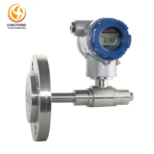
A Pressure Transmitter is a device that converts pressure (gauge pressure, absolute pressure, differential pressure) into a 4-20mA standard current signal or 0-10V voltage signal for transmission to a control system. Its core components include a pressure-sensitive element (such as a diaphragm, strain gauge, or capacitive sensor), a signal conversion circuit, and an output module. For those wondering how does a pressure transmitter work, the working principle is: the pressure-sensitive element deforms under the action of pressure, converting the pressure signal into a micro-electrical signal (voltage or current), which is then amplified, filtered, and linearized by the signal conversion circuit to output a standardized signal that is easy to transmit and process.
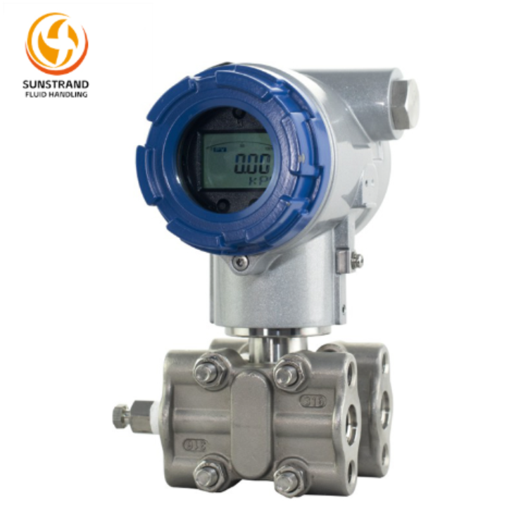
According to the measurement type, pressure transmitters can be divided into gauge pressure transmitters, absolute pressure transmitters, and differential pressure transmitters; according to the output signal type, they can be divided into current-type transmitters (4-20mA is the most common) and voltage-type transmitters. Understanding the type and core parameters of the transmitter (such as measurement range, accuracy grade, output signal type) is the premise for carrying out accurate inspection work.
Before the inspection, it is necessary to isolate the pressure transmitter from the production system to avoid the impact of the system pressure on the inspection results and prevent safety accidents. Specific operations include: closing the isolation valve in front of the transmitter, opening the vent valve to release the residual pressure in the pipeline, and confirming that the pressure at the transmitter interface is zero (for gauge pressure transmitters) or stable (for absolute pressure transmitters). For differential pressure transmitters, it is also necessary to close the positive and negative pressure chambers and balance the pressure through the balance valve.
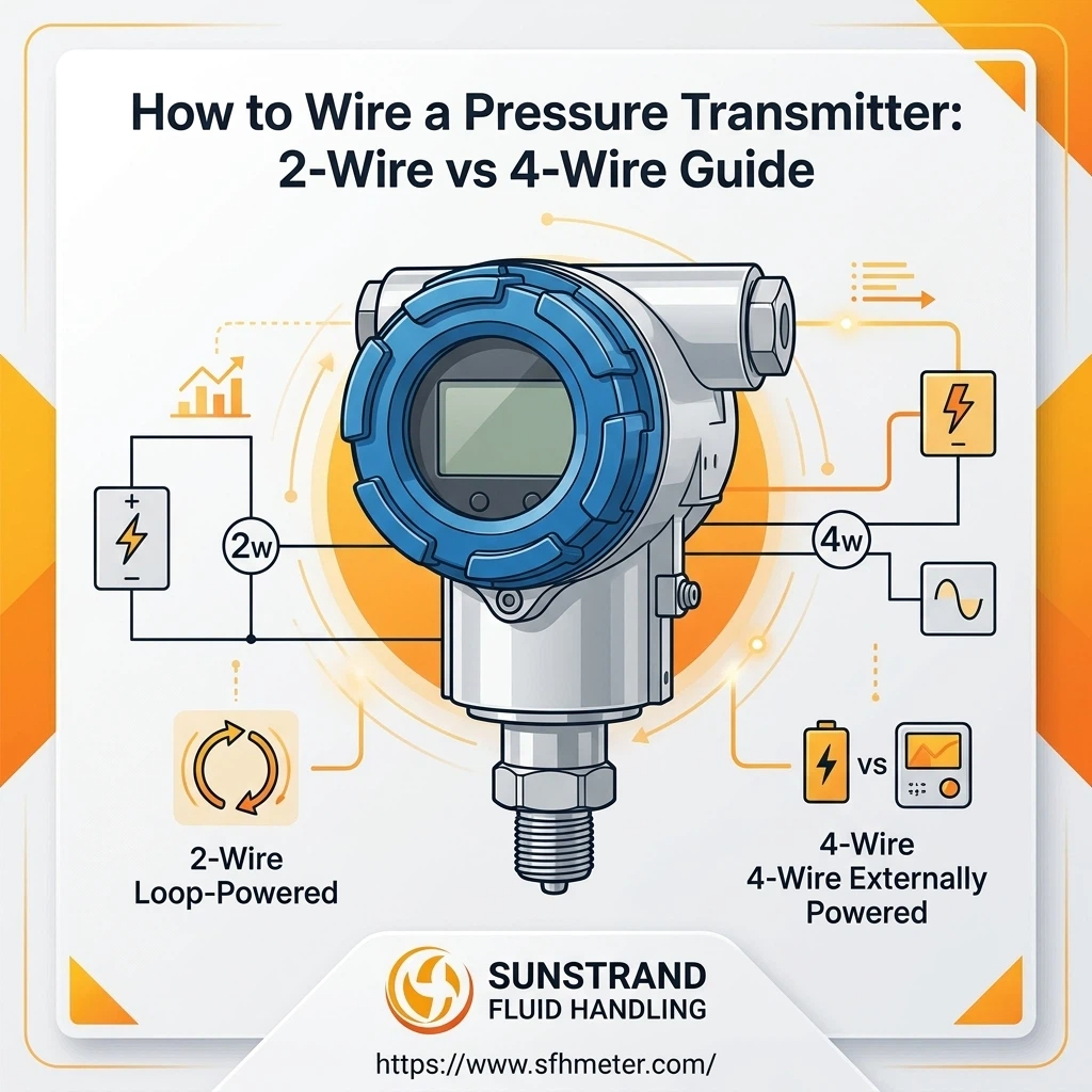
First, cut off the power supply of the transmitter to ensure the safety of the inspection personnel during the operation. Then, check the power supply parameters (voltage, current) to ensure that they match the transmitter’s rated power supply requirements (most 4-20mA transmitters use a 24V DC power supply). At the same time, prepare personal protective equipment (PPE) such as safety gloves, safety glasses, and protective shoes, and check whether the inspection site has potential safety hazards such as leakage and high temperature.
Zero verification: Under the condition of no pressure input (or atmospheric pressure for gauge pressure transmitters), connect the transmitter to a standard power supply, and measure its output signal. The standard zero output of a 4-20mA transmitter should be 4mA ± the allowable error (determined by the accuracy grade). If the deviation exceeds the allowable range, adjust the zero adjustment knob (mechanical or through the configuration software) to make the output reach the standard value.
Span verification: Input the full-scale pressure (calibration point) to the transmitter through a standard pressure source, and measure the output signal. The standard full-scale output of a 4-20mA transmitter should be 20mA ± the allowable error. If there is a deviation, adjust the span adjustment knob to correct it. After adjusting the span, it is necessary to recheck the zero point, because the zero point and span of the transmitter are interrelated.
In addition to zero and full-scale points, it is also necessary to check the output signals at 25%, 50%, and 75% of the measurement range. Input the corresponding pressure values in sequence through the standard pressure source, record the actual output signal of the transmitter, and compare it with the theoretical output value. The calculation formula of the theoretical output current of the 4-20mA transmitter is: Theoretical current (mA) = 4 + (Measured pressure / Full-scale range) × 16. The error between the actual output and the theoretical value should not exceed the allowable error of the transmitter. If the error exceeds the limit, further calibration or maintenance is required.
A multimeter is a commonly used tool for how to test pressure transmitter, which can quickly measure the output signal of the Pressure Transmitter and judge its basic working status. The specific operation steps for how to check pressure transmitter with multimeter are as follows:
Set the multimeter to the “current measurement” gear (mA gear). It should be noted that the current range of the multimeter should be greater than the maximum output current of the transmitter (usually 20mA, so the 200mA gear can be selected). For voltage-type transmitters (0-10V), set the multimeter to the “voltage measurement” gear (V gear), and select the appropriate range (such as 20V gear).
After the inspection, power off the transmitter, remove the multimeter, and reconnect the signal line correctly.
The loop check of the Pressure Transmitter is to check the integrity and working status of the entire measurement loop (including the transmitter, signal line, and control system input module). As an important part of how to check Pressure Transmitter, loop check is more comprehensive than single transmitter check, as it can better reflect the actual working effect of the Pressure Transmitter in the system.
The loop check covers the entire signal transmission path: the pressure signal collected by the transmitter → the converted standard signal (4-20mA/0-10V) → the signal line transmission → the input module of the control system (such as PLC, DCS) → the signal display on the control panel. The purpose is to check whether there is signal loss, interference, or abnormal conversion in the loop.
To complete the Pressure Transmitter accuracy check (a key part of how to test pressure transmitter), the following essential pressure transmitter calibration equipment is required. The specific parameters and functions are shown in the table below:
|
Equipment Name |
Key Parameters |
Function |
|
Standard Pressure Source |
Accuracy grade: 0.05% or higher; Range: covering the measurement range of the tested transmitter |
Provide accurate and stable pressure input for the transmitter, as the reference standard for accuracy check |
|
Multimeter |
Current range: 0-200mA; Voltage range: 0-20V; Accuracy grade: 0.5% or higher |
Measure the output current/voltage signal of the transmitter to judge whether it meets the standard requirements |
|
24V DC Power Supply |
Output voltage: 24V ± 0.5V; Current capacity: ≥ 500mA |
Provide stable power supply for the 4-20mA pressure transmitter during off-line inspection |
|
Pressure Connection Hoses & Adapters |
Material: corrosion-resistant (stainless steel); Interface type: matching the tested transmitter |
Connect the standard pressure source to the transmitter to ensure airtightness and avoid pressure leakage |
|
Configuration Software (Optional) |
Compatible with the brand and model of the tested transmitter |
Realize digital adjustment and parameter reading of the transmitter (for intelligent transmitters) |
When selecting calibration equipment, the following principles should be followed:
Environmental factors are one of the main reasons for inaccurate pressure transmitter inspection results, but they are often overlooked.
Procedural irregularities will also lead to inaccurate inspection results. Common procedural gaps include:
The accuracy check of the Pressure Transmitter is an important link to ensure the stable operation of the industrial automation system. When exploring How to Check Pressure Transmitter?, it is necessary to follow the standardized operation steps: do a good job in pre-check preparation (system isolation, power and safety confirmation), carry out zero and span verification and output signal comparison, and use appropriate pressure transmitter calibration equipment (multimeter, standard pressure source) to complete the inspection.
At the same time, it is necessary to pay attention to environmental factors and procedural norms to avoid inspection errors caused by oversight. For the entire measurement loop, how to loop check pressure transmitter is also a key point that cannot be ignored, and regular loop checks should be carried out to ensure the integrity and reliability of the loop. By mastering the core knowledge (including how does a pressure transmitter work) and operation skills of Pressure Transmitter accuracy check, and selecting appropriate pressure transmitter calibration equipment, engineers and maintenance personnel can effectively improve the inspection efficiency and accuracy, reduce the failure rate of the Pressure Transmitter, and provide a reliable guarantee for the safe and efficient operation of the production process.
For more professional solutions and high-quality pressure transmitters, you can visit Sunstrand‘s official website: https://www.sfhmeter.com/.
Q1: What is the allowable error range for pressure transmitter accuracy check?
A1: The allowable error range is determined by the accuracy grade of the transmitter. Taking a 4-20mA transmitter with an accuracy grade of 0.5% as an example, the full-scale output range is 16mA (20mA-4mA), and the allowable error is ±0.5%×16mA = ±0.08mA. Therefore, the zero output allowable range is 4mA±0.08mA, and the full-scale output allowable range is 20mA±0.08mA.
Q2: Can the pressure transmitter be checked online without system isolation?
A2: It can be checked online for loop check, but it is not suitable for accurate zero and span verification. Online loop check can only judge the working status of the entire loop under the current system pressure, but cannot accurately verify the zero point and span of the transmitter. For accurate accuracy check, it is necessary to isolate the system and carry out off-line verification with a standard pressure source.
Q3: What should I do if the output signal of the transmitter drifts during the inspection?
A3: First, check whether the inspection environment is stable (temperature, vibration, humidity), and whether the standard pressure source and power supply are stable. If the environment and equipment are normal, check whether the transmitter’s pressure chamber is blocked or leaking, and whether the signal line is interfered. If the above problems are excluded, it may be that the pressure-sensitive element of the transmitter is aging or damaged, and the transmitter needs to be disassembled for maintenance or replaced.
Q4: Is it necessary to use configuration software for pressure transmitter accuracy check?
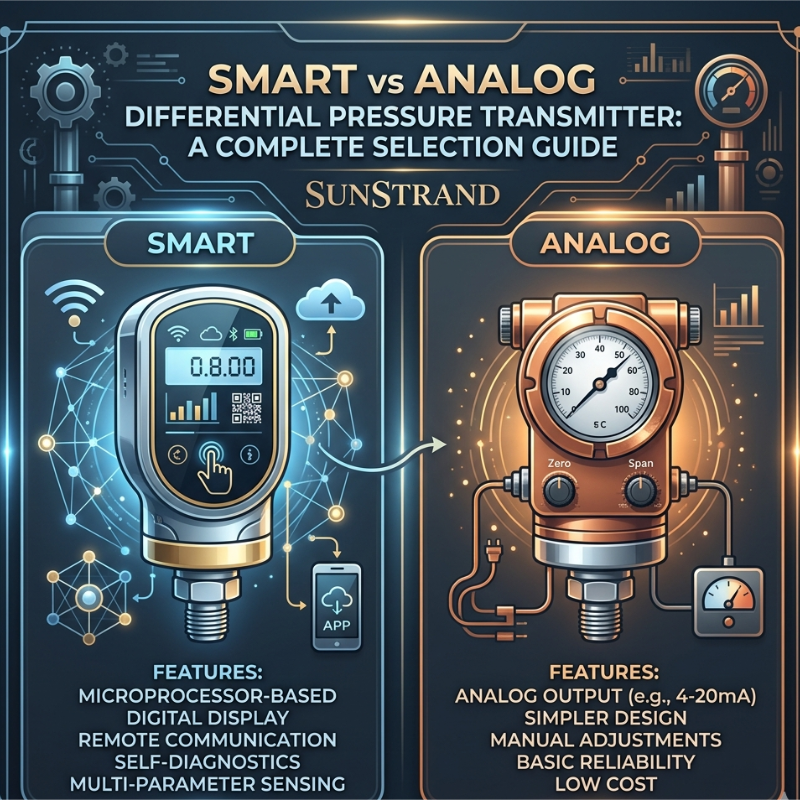
A4: It is not necessary for traditional analog transmitters (mechanical adjustment), but it is recommended for intelligent transmitters. Intelligent transmitters can realize digital adjustment through configuration software, which is more accurate and convenient than mechanical adjustment. At the same time, the configuration software can read the internal parameters of the transmitter (such as measurement range, accuracy grade, working status), which helps to better analyze the cause of the fault.