
What Is Pressure? A Quick Refresher
Pressure is the result of a force applied over a given area. Increase the force or reduce the area, and the pressure rises. In everyday life, we measure pressure in units like PSI (pounds per square inch), bar, or Pascal (Pa). For example, a standard car tyre is inflated to roughly 26 PSI.
We also experience pressure in the form of atmospheric pressure — the weight of the air column above us. At mean sea level, one bar equals atmospheric pressure. This baseline matters a great deal when choosing the right measurement type for your application.
The Three Types of Pressure Measurement
Understanding the distinctions between pressure measurement types is essential before selecting any transmitter:
| Type | Reference Point | Typical Use |
|---|---|---|
| Gauge Pressure | Atmospheric pressure | Tank pressure monitoring, tyre pressure |
| Absolute Pressure | Perfect vacuum (0 bar abs) | Boiling-point control, gas mass-flow |
| Differential Pressure | Two measured pressures — neither fixed | Flow rate, level, filter monitoring |
Differential pressure (DP) is the difference between any two measured pressures — it is not referenced to atmosphere or vacuum. An increase in differential pressure occurs if the high-side pressure rises or if the low-side pressure drops. Unlike absolute pressure transmitters differential measurement ignores the absolute value on either port; it only cares about the gap between them.
Not sure which pressure measurement type suits your application?
Sunstrand’s application engineers can help you choose between gauge, absolute, and differential configurations for your specific process conditions — at no cost.
What Is a Differential Pressure Transmitter?
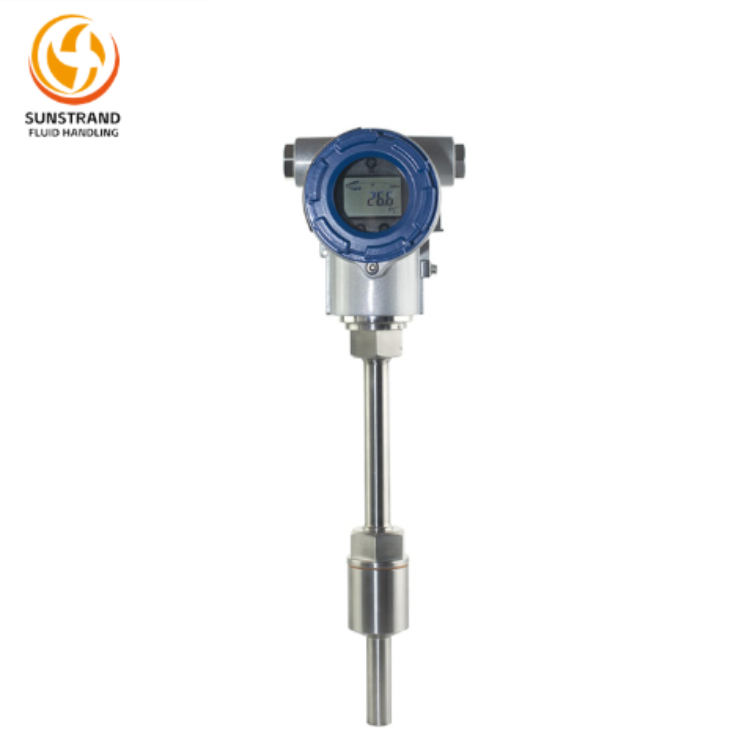
The most common and useful industrial pressure measuring instrument is the differential pressure transmitter. This device senses the pressure difference between its two ports — labelled High (H) and Low (L) — and converts it into a standardised output signal proportional to a calibrated pressure range.
The “High” and “Low” labels do not mean the H-port must always see greater pressure than the L-port. They indicate the direction of output signal change: pressure rising at H drives output up; pressure rising at L drives output down. This flexibility lets engineers connect a single DP transmitter for both direct-acting and reverse-acting measurement scenarios.
Key Performance Parameters
- Pressure range: The span between minimum and maximum measurable differential pressure (e.g., 0–100 mbar, 0–10 bar).
- Output signal: Typically 4–20 mA DC; some models add HART, Profibus, or Modbus communication.
- Ambient temperature: Specified operating range that the transmitter can withstand without accuracy degradation.
- Common-mode pressure / MWP: Maximum line (gauge) pressure both ports can withstand simultaneously — often 100× the differential range.
Differential Pressure Transmitter Construction
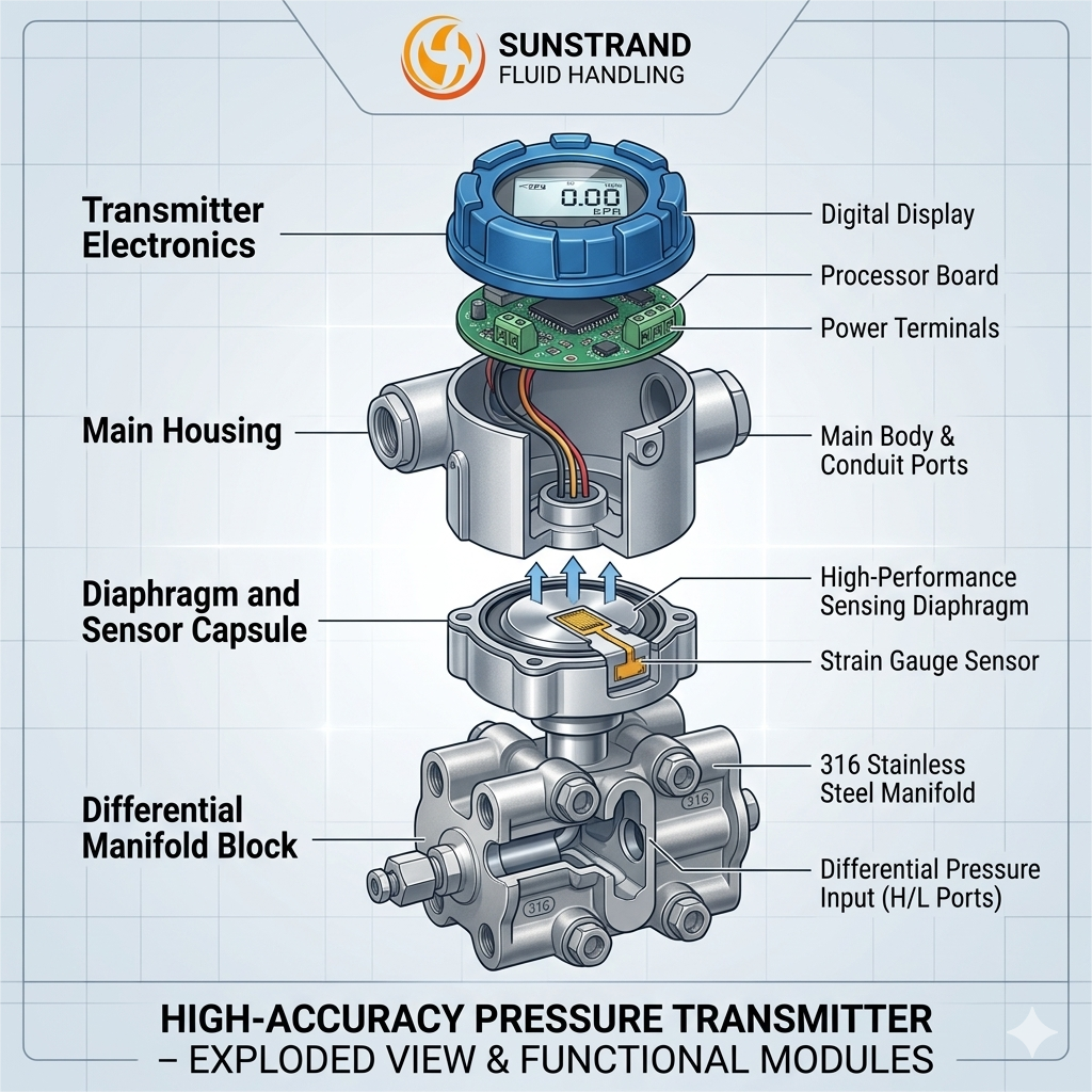
A standard industrial DP transmitter consists of three functional parts:
1. Pressure-Sensing Element (Lower Housing)
A diaphragm — a flexible metal membrane — sits between the two pressure inlet ports. When a differential pressure exists, the diaphragm deflects. This physical deflection is converted into an electrical signal by one of the following sensor types:
- Strain gauge — bonded resistors change resistance as the diaphragm flexes (piezoresistive principle)
- Differential capacitance — diaphragm movement changes the gap between capacitor plates, altering capacitance
- Vibrating wire — wire tension changes with diaphragm displacement, altering resonant frequency
The sensor output (a millivolt-level signal) is proportional to the applied differential pressure across the calibrated pressure range.
2. Electronic Unit (Upper Housing)
The millivolt signal from the sensing element is too small for direct transmission. The electronics amplify and condition it to a usable range — typically 0–5 V, 0–10 V, or 4–20 mA. Modern electronics also apply temperature compensation to counteract the effects of changing ambient temperature on sensor output.
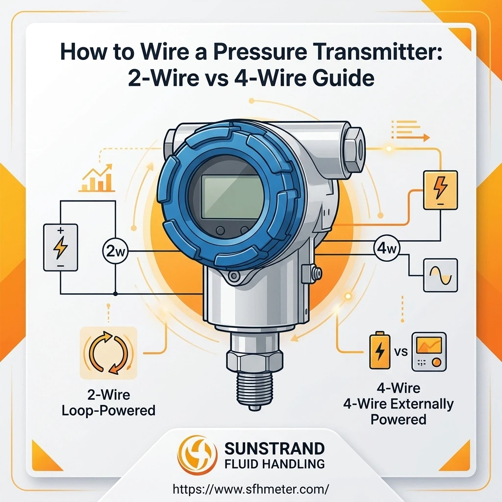
3. 2-Wire 4–20 mA Current Loop Transmitter
The industry-standard output signal is a 4–20 mA current loop. 4 mA represents the lower end of the pressure range (0% of span), and 20 mA represents the upper end (100% of span). This current signal is immune to voltage drop in long cable runs and is unaffected by load impedance variation — ideal for large industrial sites. HART FSK digital communication is often superimposed on the same two wires.
Where Is Differential Pressure Measurement Used?
DP transmitters are the backbone of many inferential measurements. Because differential pressure relates predictably to fluid behaviour, engineers use it to infer flow rate, flow level density viscosity, and even temperature — without direct contact with the process fluid in many installations.
A. Flow Rate Measurement (Most Common Application)
This is one of the most common applications in industrial automation. A primary element — such as an orifice plate, venturi tube, flow nozzle, or pitot tube — introduces a controlled constriction into the pipe. As flow increases, the pressure drop across the constriction increases according to Bernoulli’s equation (pressure drop ∝ flow²).
The DP transmitter acts as the secondary element, measuring the differential pressure produced by the primary element as accurately as possible. It is critical that the measurement is not influenced by changes in static line pressure, fluid temperature, or ambient temperature — a well-designed transmitter achieves this through common-mode rejection and thermal compensation. The output signal may include square-root extraction to linearise the flow signal, although this function is increasingly handled by a DCS or flow computer downstream.
B. Liquid Level Measurement
Liquids generate hydrostatic pressure proportional to their depth. By connecting the high side of a DP transmitter to the bottom of a vessel and the low side to the vapour space at the top, the transmitter measures only the pressure produced by the liquid column — ignoring any gas blanket pressure above the liquid as a common-mode signal. This technique works whether the vessel is open to atmosphere or operating under high process pressure.
C. Filter and Equipment Monitoring
As a filter clogs, the pressure drop across it increases. A DP transmitter connected across the filter inlet and outlet continuously monitors this differential — triggering maintenance alerts before a blocked filter causes process disruption or equipment damage.
D. Other Common Applications
- Oil and gas flow metering — onshore, offshore, and subsea
- Water and effluent treatment — filter and membrane monitoring
- Sprinkler system supervision
- Remote sensing of steam and hot-water heating circuits
- Pump differential monitoring and cavitation detection
- HVAC air-flow and clean-room differential pressure control
Need a DP transmitter for flow, level, or filter monitoring?
Sunstrand supplies HART-compatible differential pressure transmitters with ranges from 0–1 mbar to 0–700 bar, SIL-rated options available. Request a datasheet or quote today.
Absolute Pressure Transmitters vs. Differential: When to Use Which
A common point of confusion for beginners is when to choose absolute pressure transmitters differential versus true differential instruments. Here’s a quick decision guide:
- Use a differential DP transmitter when you need the difference between two process points — flow across an orifice plate, level in a pressurised vessel, or pressure drop across equipment.
- Use an absolute pressure transmitter when the reference must be a perfect vacuum — vacuum distillation, mass flow of gases, or any application where atmospheric variation would introduce unacceptable error.
- Use a gauge pressure transmitter when you only need pressure relative to local atmosphere — most tank level applications on open vessels, tyre-inflation rigs, or hydraulic system monitoring.
How to Select the Right Differential Pressure Transmitter
When specifying a DP transmitter for your application, consider these parameters:
- Differential pressure range: Select the lowest range that covers your maximum expected differential — smaller spans typically deliver better accuracy as a percentage of reading.
- Maximum working pressure (MWP): Must exceed maximum static line pressure, even if the differential is small.
- Process fluid compatibility: Wetted materials (316 SS, Hastelloy, tantalum) must be compatible with your fluid and temperature.
- Output signal and protocol: 4–20 mA + HART is universal; Profibus PA or Foundation Fieldbus may be required in certain DCS environments.
- Ambient temperature rating: Verify operating and storage temperature ranges match your site conditions.
- Certifications: ATEX / IECEx for hazardous areas; SIL 2/3 for safety instrumented systems.
FAQs
Ready to Source Differential Pressure Transmitters for Your Plant?
Sunstrand specialises in industrial DP transmitters for flow, level, and pressure monitoring across oil & gas, water treatment, power generation, and chemical processing. Our team can help you select, size, and commission the right instrument — from standard HART units to SIL-rated safety transmitters.
About Sunstrand
Sunstrand is an industrial instrumentation supplier focused on differential pressure, flow, and level measurement solutions for B2B clients in process industries worldwide. Our product range includes differential pressure transmitters, vortex flowmeters, magnetic flowmeters, and multivariable transmitters — all supported by application engineering, factory calibration, and global logistics.